IAE Academy

GATE EC · EE · IN

Circuit laws, sources, and node and mesh analysis

This topic covers what every circuit problem is built from: the V-I laws and stored energy of R, L, C and coupled inductors; ideal, practical and dependent sources; Kirchhoff's laws; series-parallel and star-delta reduction; and the two standard solution methods, nodal analysis (with supernodes) and mesh analysis (with supermeshes). Every later Networks topic (theorems, transients, sinusoidal steady state, two-ports) starts by writing these equations. Getting the sign conventions and the dependent-source constraints right here is what makes those later answers come out right.

25 previous-year questions · 24 solved · 5 practice questions

Circuit elements, sign convention and energy storage

Passive sign convention (used throughout these notes). Mark an element's voltage with + and − terminals and take its current as entering the + terminal. Then is the power absorbed by the element, and means the element is delivering power. A resistor () always absorbs power. An ideal inductor or capacitor only stores energy and gives it back, so over one period of a periodic steady state its average power is zero.

RESISTOR (OHM'S LAW)

Linear resistor, passive sign convention. Conductance (siemens), so .

INDUCTOR

Passive sign convention. The stored energy depends only on the present current. In DC steady state , so an inductor behaves as a short circuit.

CAPACITOR

Passive sign convention. In DC steady state , so a capacitor behaves as an open circuit.

CONTINUITY OF CAPACITOR VOLTAGE AND INDUCTOR CURRENT

is the instant just before the switching and the instant just after. The rule holds whenever the capacitor current and the inductor voltage stay finite (no impulses). That is guaranteed when the sources are finite and the switching creates no loop made only of capacitors and ideal voltage sources and no cut-set made only of inductors and ideal current sources. If such a loop is formed, the capacitor voltages are forced to jump (solve with charge conservation); if such a cut-set is formed, the inductor currents are forced to jump (solve with flux-linkage conservation). Capacitor current, inductor voltage and resistor quantities CAN jump at .

SERIES AND PARALLEL COMBINATIONS

Inductors without mutual coupling. Two resistors in parallel give , and two capacitors in series give . Series capacitors that start uncharged carry equal charge.

COUPLED INDUCTORS (DOT CONVENTION)

Each coil uses the passive sign convention for its own and . Take +M when both currents enter (or both leave) the dotted terminals, and −M when one enters a dot and the other leaves one. means perfect coupling.

COUPLED INDUCTORS IN SERIES AND PARALLEL; STORED ENERGY

For : upper sign = aiding (in series, the current enters both dotted terminals in turn; in parallel, the dotted terminals are joined together), lower sign = opposing. For the energy: when and both enter (or both leave) the dotted terminals, otherwise. for all currents, which is why .

COUPLED COILS WITH A COMMON TERMINAL (T-EQUIVALENT)

Two coupled coils that share one terminal can be replaced by an uncoupled T network: series arm on coil 1's side, series arm on coil 2's side, and shunt arm to the common terminal. "Like terminals joined" means both dotted ends (or both undotted ends) meet at the common terminal. A negative inductance in the model is only a mathematical element; the behaviour at the three terminals is exact.

CHARGE SHARING BETWEEN TWO CAPACITORS

Capacitors charged to and are connected in parallel, + plate to + plate. If they are joined with opposite polarities, replace by . The total charge is conserved; the energy is dissipated in the connecting resistance, whatever its value.

EXAM TIP

Charge is conserved when capacitor voltages are forced to jump; energy is not. Connect a capacitor charged to across an identical uncharged : the charge is shared, so each ends at and the total stored energy is . Half of the initial is dissipated in the connecting resistance, however small that resistance is. Solve such problems with charge conservation, never energy conservation.

Ideal, practical and dependent sources

An ideal voltage source holds its terminal voltage at whatever current the circuit draws. An ideal current source drives whatever voltage appears across it. To deactivate an independent source (in superposition, or when finding a Thevenin resistance), replace a voltage source by a short circuit and a current source by an open circuit.

A practical source has losses. A practical voltage source is with a series internal resistance ; a practical current source is with a shunt resistance . In the table, is the current delivered out of the + terminal (source convention).

Source

Model

Terminal V-I relation

Open-circuit voltage

Short-circuit current

Ideal voltage source

alone

for every

Not defined (shorting it is not allowed)

Practical voltage source

in series with

Ideal current source

alone

for every

Not defined (opening it is not allowed)

Practical current source

in parallel with

Plotted with on the vertical axis and on the horizontal axis, a practical source is a straight line from its open-circuit point to its short-circuit point, with slope (or for the current-source model; the two models describe the same source when and ). It approaches an ideal voltage source (a horizontal line) as , and an ideal current source (a vertical line) as .

SOURCE TRANSFORMATION

in series with is equivalent at its two terminals to in parallel with the same . The current-source arrow points toward the terminal that was + on the voltage source. The two are equivalent only at the terminals: the power dissipated inside differs. An ideal source (no ) cannot be transformed. A dependent source can be transformed the same way, provided its controlling variable is not the current or voltage of the resistor being transformed, because that quantity changes in the transformation.

Redundant and forbidden connections

  1. Any element connected directly in parallel with an ideal voltage source changes nothing elsewhere in the circuit, so it can be removed (left open) for the analysis. It does change the source's current and power. Keep it if its current controls a dependent source.

  2. Any element connected in series with an ideal current source changes nothing elsewhere, so it can be shorted for the analysis. It does change the voltage across the current source and its power. Keep it if its voltage controls a dependent source.

  3. Ideal voltage sources in series add algebraically; ideal current sources in parallel add algebraically.

  4. Two ideal voltage sources of different values in parallel, or two ideal current sources of different values in series, violate KVL or KCL, and such a circuit has no solution. More generally, a loop made only of ideal voltage sources must satisfy KVL by itself, and a cut-set made only of ideal current sources must satisfy KCL by itself.

Type

Output

Controlled by

Gain and unit

VCVS

a voltage elsewhere in the circuit

, dimensionless

CCVS

a current elsewhere in the circuit

, ohms (transresistance)

VCCS

a voltage

, siemens (transconductance)

CCCS

a current

, dimensionless

Handling a dependent source in analysis

  1. Write the node or mesh equations treating it exactly like an independent source of the same kind (voltage or current).

  2. Add one constraint equation that expresses its controlling variable ( or ) in terms of the unknowns (node voltages or mesh currents).

  3. Never deactivate it in superposition or when finding a Thevenin or Norton resistance. It stays in the circuit; apply a test source at the terminals instead.

  4. It can deliver or absorb power, and a resistor network containing it can show a negative or zero equivalent resistance.

EXAM TIP

Read the controlling variable with its stated direction. If is defined as flowing from a to b and the actual current flows from b to a, then is negative, and the dependent source's value changes sign with it. Rewriting the controlling variable with the wrong direction is the usual source of sign errors in dependent-source questions.

Kirchhoff's laws, series-parallel reduction and division rules

A node is a point where two or more elements meet. A loop is any closed path. A mesh is a loop with no other loop inside it, which is defined only for a planar drawing. Kirchhoff's laws hold for every lumped circuit, linear or nonlinear, time-invariant or time-varying, because they express conservation of charge (KCL) and the fact that voltage between two points does not depend on the path (KVL).

KIRCHHOFF'S CURRENT LAW

Equivalently, total current entering = total current leaving. It also holds for a closed surface enclosing several nodes, which is the basis of the supernode.

KIRCHHOFF'S VOLTAGE LAW

Count a drop as positive when the loop crosses an element from + to −. It holds for any closed path, including one through a current source or across an open gap (the voltage there is then an unknown).

VOLTAGE DIVISION

Resistors in series carrying the same current, with nothing else drawing current from the tap. For impedances, replace by .

CURRENT DIVISION

Branches in parallel across the same voltage. With two branches, the current in one is proportional to the OTHER branch's resistance.

CAPACITIVE AND INDUCTIVE DIVIDERS

Series capacitors initially uncharged: each carries the same charge, so the smaller capacitor takes the larger voltage. Series inductors without mutual coupling.

BALANCED WHEATSTONE BRIDGE

A bridge with arms A–C–B and A–D–B and an element between C and D. When the bridge is balanced and the C–D element contains no source, that element carries no current and can be removed or replaced by a short without changing anything else.

EXAM TIP

Symmetry and equipotentials. Nodes at the same potential, whether because a bridge is balanced or because the network is symmetric about its input terminals, can be joined, and any source-free element between them can be removed. Check for this before using star-delta or nodal analysis.

CUBE OF TWELVE EQUAL RESISTORS

Resistance between two corners of a cube whose twelve edges are each : opposite corners of the cube, opposite corners of one face, and the two ends of one edge. Each follows from symmetry: join the corners that are at equal potential, then reduce.

INFINITE LADDER NETWORK

A ladder that starts at the input with a series resistor , then a shunt resistor , repeated without end. Adding one more section does not change the input resistance, so , and the formula is the positive root. If the ladder starts with the shunt arm instead, its input resistance is with from the formula.

EXAM TIP

The divider formula fails once a load draws current from the tap. A 10 kΩ–10 kΩ divider on 10 V gives 5 V with nothing connected. Put a 10 kΩ load across the lower resistor and the lower arm becomes 5 kΩ, so the output drops to V. Combine the load in parallel first, then divide.

Star-delta (wye-delta) transformation

When resistors form a bridge or a mesh with no series or parallel pair left to combine, convert a delta (Δ: three resistors forming a triangle between nodes a, b, c) into an equivalent star (Y: three resistors from a, b, c to a new internal node), or the reverse. Label each star resistor by the node it touches (, , ) and each delta resistor by the pair of nodes it joins (, , ). The two networks are equivalent only as seen from terminals a, b and c.

The same formulas hold for impedances at a single frequency. For inductors without mutual coupling they apply to directly; for capacitors, apply them to (the reactance is ), never to itself.

DELTA TO STAR

Star arm at a node = product of the two delta resistors touching that node ÷ sum of all three delta resistors.

STAR TO DELTA

Delta resistor between two nodes = sum of the pairwise products of the star arms ÷ the star arm at the OPPOSITE (third) node. Equivalently, .

BALANCED (EQUAL-ARM) CASE

All three arms equal. The same relation holds for equal impedances at a single frequency, for example a balanced three-phase load.

STAR TO DELTA IN CONDUCTANCE FORM

Written with conductances, the star-to-delta rule has the same shape as the delta-to-star rule written with resistances (duality).

WORKED EXAMPLE

A bridge network has nodes A, B, C, D with , , , and . Find the equivalent resistance between A and B.

Solution
  1. Balance check: , but . The bridge is not balanced, so the 30 Ω arm carries current and no series-parallel reduction is possible.

  2. Convert the delta A–C–D (10, 20 and 30 Ω, sum 60 Ω) into a star with internal node N: , , .

  3. Path N–C–B is and path N–D–B is . They are in parallel: .

  4. .

  5. Cross-check by nodal analysis with 1 V at A and B grounded. Node C gives and node D gives , so V and V. Input current A, and .

Answer:

EXAM TIP

Star-delta preserves only the behaviour seen at the three terminals. The currents and powers in the new resistors are not those of the original ones. To find a current inside the transformed part, go back to the original network and use the terminal voltages you found.

Nodal analysis and mesh analysis

Both methods reduce a circuit to a set of simultaneous linear equations with as few unknowns as possible.

  • Nodal analysis uses node voltages, measured from a chosen reference node, and KCL. It works for any circuit.
  • Mesh analysis uses mesh currents, each circulating around one window of a planar drawing, and KVL. It works only for planar circuits. A branch shared by meshes and carries the difference of their two mesh currents. For a nonplanar circuit, use loop (tie-set) analysis on the fundamental loops of a tree instead; it needs the same number, , of loop currents.

Nodal analysis: procedure

  1. Pick a reference node (ground), usually the one with the most elements or the one shared by most voltage sources. Label the other node voltages

  2. A voltage source from a node to the reference fixes that node's voltage, so no equation is written there.

  3. At every other node write KCL: sum of currents leaving through elements = sum of source currents injected into the node. A resistor between nodes and carries away from node .

  4. Supernode: a voltage source (independent or dependent) between two non-reference nodes. Enclose both nodes and the source in one closed surface and write ONE KCL for that surface; the source current is inside the surface and does not appear. Add the constraint , with the + terminal at a.

  5. Any element connected in parallel with the supernode's source (between the same two nodes) is also inside the surface and does not appear in its KCL.

  6. For every dependent source, write its controlling variable in terms of node voltages.

  7. Solve, then find branch currents and powers from the node voltages.

NODAL EQUATIONS BY INSPECTION

Valid for circuits with only resistors and independent current sources. = net source current injected INTO node . The matrix is symmetric; a dependent source breaks the symmetry and has to be added by hand.

Mesh analysis: procedure

  1. Check that the circuit is planar. Assign a mesh current to each window, all clockwise.

  2. A current source in a branch that belongs to one mesh only (on the outer boundary) fixes that mesh current, so no KVL is written for that mesh.

  3. In every other mesh write KVL: sum of drops = sum of source rises, going in the mesh direction. A resistor shared by meshes and has a drop of when traversed in mesh 's direction.

  4. Supermesh: a current source shared by two meshes. Write ONE KVL around the loop formed by both meshes with the shared branch left out. Add the constraint that the source current equals the difference of the two mesh currents, with signs taken from the direction of its arrow.

  5. Any element in series with that current source does not appear in the supermesh equation.

  6. For every dependent source, write its controlling variable in terms of mesh currents.

MESH EQUATIONS BY INSPECTION

Valid when all mesh currents are clockwise and the circuit has only resistors and independent voltage sources. = algebraic sum of the source voltages driving current in mesh 's direction (rises positive). The matrix is symmetric unless dependent sources are present.

NUMBER OF KCL OR KVL EQUATIONS TO WRITE

= nodes and = branches of a connected circuit, counting every element as a separate branch. = voltage sources (independent or dependent); each fixes a node voltage or supplies a supernode constraint, so one KCL equation fewer is needed. = current sources (independent or dependent); each fixes a mesh current or supplies a supermesh constraint. A dependent source's constraint is still expressed in the unknowns, so it has to be substituted, not just read off. Assumes no loop made only of voltage sources and no cut-set made only of current sources. Choose the method that needs fewer equations.

Feature

Nodal analysis

Mesh analysis

Unknowns

Node voltages from a reference

Mesh currents (clockwise)

Law written

KCL at each non-reference node

KVL around each mesh

Equations to write

Source that simplifies

Voltage source to the reference: that node voltage is known

Current source in one mesh only: that mesh current is known

Source that needs special care

Voltage source between two non-reference nodes: supernode

Current source shared by two meshes: supermesh

Applies to

Any circuit, planar or not

Planar circuits only (use loop analysis otherwise)

Usually shorter when

Many parallel branches and current sources

Many series elements and voltage sources

WORKED EXAMPLE

Nodes 1, 2, 3 and reference 0. A 4 A independent current source drives current from node 0 into node 1. Resistors: from node 1 to 0, from node 1 to node 2, from node 2 to 0, and from node 3 to 0. A current-controlled voltage source is connected between node 2 (+) and node 3 (−), with value volts, where is the current in the resistor from node 1 to node 2. Find the node voltages and the power absorbed by the dependent source.

Solution
  1. The CCVS is between two non-reference nodes, so nodes 2 and 3 form a supernode. The unknowns are , and the controlling variable is .

  2. KCL at node 1: , which gives .

  3. Constraint: , so .

  4. KCL for the supernode (currents leaving the surface): . Multiply by 6 and substitute : , so .

  5. Then , so V, V, V. This gives A and a source voltage V.

  6. Current through the CCVS: by KCL at node 3, the current arriving from the source equals the current leaving through the 2 Ω resistor, A. This 1 A flows through the source from node 2 to node 3, so it enters the + terminal. Power absorbed W.

  7. Power balance check: the 4 A source delivers W. The resistors absorb W and the CCVS absorbs 4 W, a total of 40 W.

Answer: V, V, V; the CCVS absorbs 4 W.

WORKED EXAMPLE

Draw a two-window circuit on a reference rail 0 with nodes a, b, c, m. Left leg: a 24 V source from 0 to a (+ at a). Top: from a to b and from b to c. Right leg: from c to 0. Middle leg: a 3 A current source from 0 to m (arrow pointing up into m) in series with from m to b. With clockwise mesh currents (left window) and (right window), find both mesh currents and the power delivered by the current source.

Solution
  1. The current source is in the branch shared by both meshes, so use a supermesh. In the middle leg flows upward and downward, so the constraint is .

  2. Supermesh KVL around the outer loop 0 → a → b → c → 0, leaving out the whole middle leg including its 5 Ω: , i.e. .

  3. Substitute : , so A and A. The negative sign means 0.5 A actually flows anticlockwise in the left mesh, into the + terminal of the 24 V source, which therefore absorbs W.

  4. Node voltages: V. In the middle leg, 3 A flows up through the 5 Ω from m to b, so V.

  5. The current source has 40 V across it, and here its arrow-head end m is the higher-potential terminal. Its 3 A leaves from that higher-potential terminal, so it delivers W.

  6. Check: power absorbed W (the 2 Ω, 4 Ω, 6 Ω and 5 Ω resistors and the 24 V source).

Answer: A, A; the current source delivers 120 W. The 5 Ω in series with the current source changes that power but not the mesh currents.

EXAM TIP

Finish every nodal or mesh answer with a power balance: the power absorbed, summed over all elements including the sources, must be zero. A wrong sign in a source or dependent-source term will generally break the balance, so the check exposes it.

Power, energy, ratings, efficiency and practical sources

With the passive sign convention, is the power absorbed and energy is its time integral. Power is conserved at every instant in any circuit: the powers absorbed by all elements add up to zero, so the total delivered by the sources equals the total absorbed by everything else. Energy consumption is billed in kilowatt-hours.

POWER, ENERGY AND POWER BALANCE

Passive sign convention. J.

SAFE CURRENT AND VOLTAGE OF A RATED RESISTOR

The power rating is the largest power a component can dissipate continuously without overheating. In series, the smallest limits the whole string; in parallel, the smallest limits.

EFFICIENCY

Losses are the power dissipated in resistances, for example in conductors and in a source's internal resistance.

PRACTICAL SOURCE FEEDING A RESISTIVE LOAD

is the fraction of the power generated by the ideal part, , that reaches . It approaches 100% as .

MAXIMUM POWER FROM A PRACTICAL SOURCE

Fixed and with a variable resistive load. Maximum power transfer and maximum efficiency happen at different operating points. If instead is fixed and can be chosen, is largest at , not at : the matching condition applies only when the load is the variable.

BATTERY WITH INTERNAL RESISTANCE

= EMF (the open-circuit voltage, which depends on the state of charge), = internal resistance, = magnitude of the current. Short-circuit current is . Stored energy ≈ nominal voltage × capacity in Ah, which gives Wh.

SOLAR CELL (IDEAL SINGLE-DIODE MODEL)

Generator convention: is the current delivered out of the + terminal. is the photocurrent (proportional to irradiance), the diode saturation current, the ideality factor, and mV at 300 K. Series and shunt resistances are neglected.

FILL FACTOR AND CELL EFFICIENCY

and are taken at the maximum-power point (the knee of the I-V curve). = irradiance in W/m², = cell area in m².

Reading the solar-cell curve. At low voltage the cell behaves almost like a current source (). Near the current collapses, and the cell behaves almost like a voltage source. The power is zero at both ends of the curve and peaks at the knee. Higher irradiance raises roughly in proportion but raises only logarithmically. Higher cell temperature lowers .

EXAM TIP

Power ratings do not simply add. Two 1 W resistors in series can dissipate 2 W in total only if they are equal. With unequal values, the one with the smaller (the larger resistance, for equal ratings) reaches its rating first and limits the whole string.

EXAM TIP

Maximum power transfer is not maximum efficiency. At half the generated power is lost inside the source. Power systems are run with for efficiency, while signal circuits are matched () for maximum power.

Network topology in brief

Replace each element by a line segment to get the graph of the network, with branches and nodes. A source together with its series resistance is often drawn as one branch. Some questions instead draw the graph with the independent sources deactivated (voltage sources shorted, current sources opened); follow the convention the question states.

  • A tree is a connected subgraph that contains all nodes and no closed loop. Its branches are twigs; the remaining branches are links (chords).
  • Adding one link to a tree creates exactly one closed loop, called a fundamental loop (tie-set).
  • Removing one twig splits the tree into two parts. The branches joining those two parts form a fundamental cut-set.

TWIGS AND LINKS OF A CONNECTED GRAPH

For a graph with separate parts: twigs and links .

INDEPENDENT EQUATIONS

Connected graph. For a planar graph, is also the number of meshes (windows).

NUMBER OF POSSIBLE TREES

= reduced incidence matrix (one row deleted). A complete graph on nodes has branches.

Topology matrices

  1. Incidence matrix : size . With the convention used here, an entry is if the branch leaves the node, if it enters, and 0 otherwise, so each column has exactly one and one (some texts use the opposite signs). The reduced incidence matrix is with rank for a connected graph. KCL: .

  2. Fundamental loop (tie-set) matrix : size , one row per link, each loop oriented along its link. Each fundamental loop contains exactly one link. KVL: .

  3. Fundamental cut-set matrix : size , one row per twig, each cut-set oriented along its twig. Each fundamental cut-set contains exactly one twig. KCL: .

  4. The link currents are a complete set of independent currents (the basis of loop and mesh analysis). The twig voltages are a complete set of independent voltages (the basis of cut-set and nodal analysis).

RELATIONS BETWEEN THE TOPOLOGY MATRICES

= link currents, = twig voltages, = identity matrix. The last line holds with the branches numbered twigs first and links after, each fundamental loop oriented along its link and each fundamental cut-set oriented along its twig.

EXAM TIP

To test whether a set of branches is a tree, check three things: it has exactly branches, it touches every node, and it contains no loop. A set of branches that contains a loop must leave some node unconnected, so it is not a tree.

PREVIOUS-YEAR QUESTIONS

25 questions from the EC, EE and IN papers

Try each question first, then open the answer. One shows the official answer only. We placed each question under a topic ourselves; the exam paper does not label topics.

See these papers in full: GATE ECE 2026 · GATE ECE 2025 · GATE ECE 2024 · GATE ECE 2023 · GATE ECE 2022 · GATE ECE 2018 · GATE EE 2026 · GATE EE 2025 · GATE EE 2024 · GATE EE 2023 · GATE EE 2022 · GATE EE 2020 · GATE EE 2018 · GATE IN 2026 · GATE IN 2024 · GATE IN 2020 · GATE IN 2018

GATE 2026 EC Q.30

GATE 2026 · ECQ.30 · 1 mark · NAT

The output voltage (in Volt) for the network given in the Figure is ____. (rounded off to two decimal places)
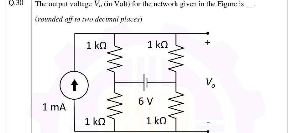
GATE 2026 EC question 30: Four nodes: top rail T, bottom rail G, and two middle nodes A (left) and B (right).Tap to open full size
Figure from the GATE 2026 EC paper. It is part of the question.
Figure description

Four nodes: top rail T, bottom rail G, and two middle nodes A (left) and B (right). A 1 mA independent current source sits on the far left between G and T, with its arrow pointing up (current driven from the bottom rail into the top rail). A continuous top wire joins the source's upper terminal, the top of the left resistor column, the top of the right resistor column and the output terminal marked +. A continuous bottom wire joins the source's lower terminal, the bottoms of both columns and the output terminal marked -. Left column: a 1 kΩ resistor from T down to node A, then a 1 kΩ resistor from A down to G. Right column: a 1 kΩ resistor from T down to node B, then a 1 kΩ resistor from B down to G. A 6 V battery is connected horizontally between A and B. Its long plate (positive terminal) faces A and its short plate (negative terminal) faces B, so V_A - V_B = 6 V. V_o is the voltage between the top rail (+) and the bottom rail (-).
Answer and solution
GATE 2026 EC Q.30: answer and solution

GATE 2026 EE Q.23

GATE 2026 · EEQ.23 · 1 mark · MCQ

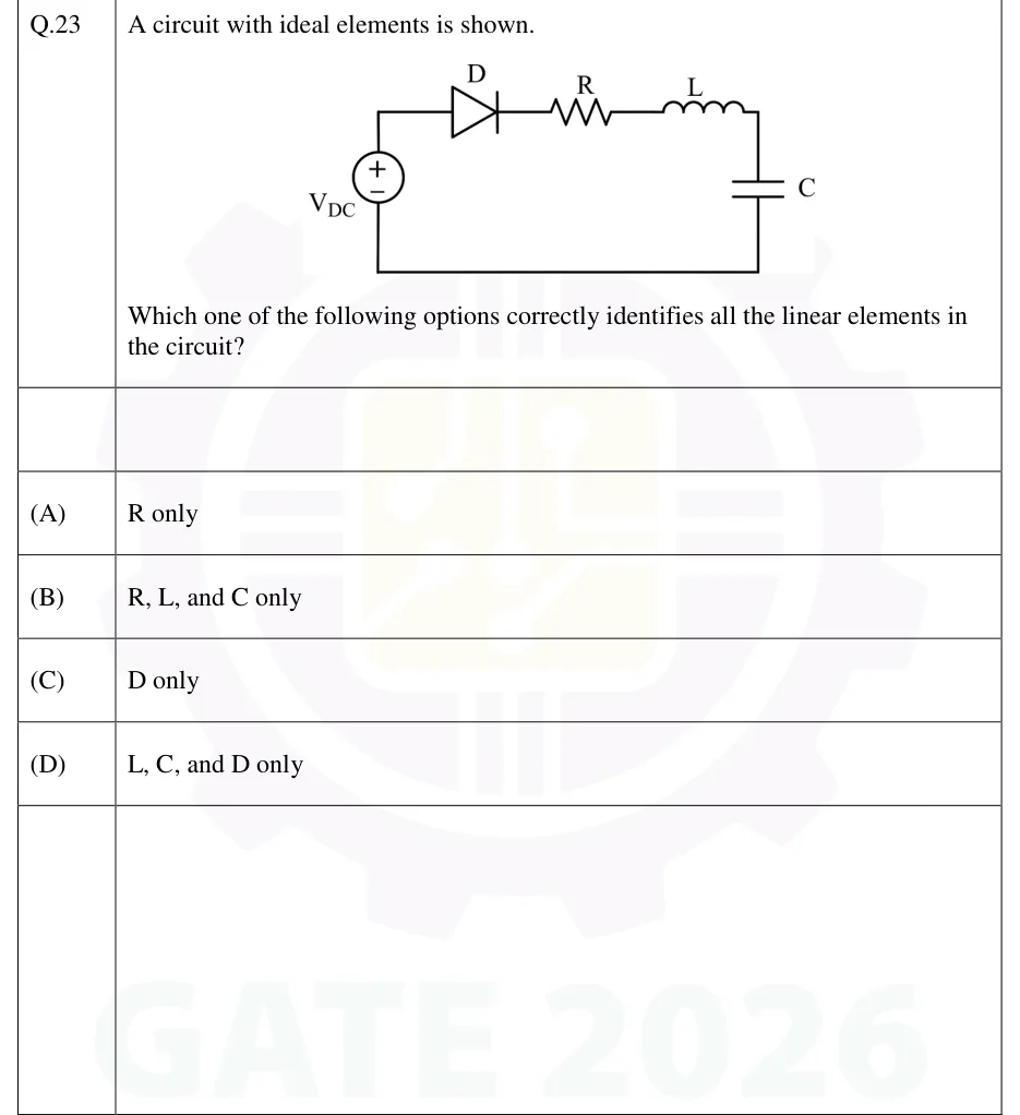
A circuit with ideal elements is shown.

[Figure]

Which one of the following options correctly identifies all the linear elements in the circuit?

GATE 2026 EE question 23: A single series loop.Tap to open full size
Figure from the GATE 2026 EE paper. It is part of the question.
Figure description

A single series loop. On the left side sits a DC voltage source labelled V_DC, drawn as a circle with + at the top and − at the bottom. From the source's + terminal the wire goes up and then right along the top branch through, in order: a diode D (anode on the left, cathode on the right, so it conducts clockwise away from the + terminal), then a resistor R, then an inductor L. The wire then comes down the right side through a capacitor C and returns along the bottom wire to the source's − terminal. No element values are given.

  1. (A)

    R only

  2. (B)

    R, L, and C only

  3. (C)

    D only

  4. (D)

    L, C, and D only

Answer and solution
GATE 2026 EE Q.23: answer and solution

GATE 2026 EE Q.25

GATE 2026 · EEQ.25 · 1 mark · MCQ

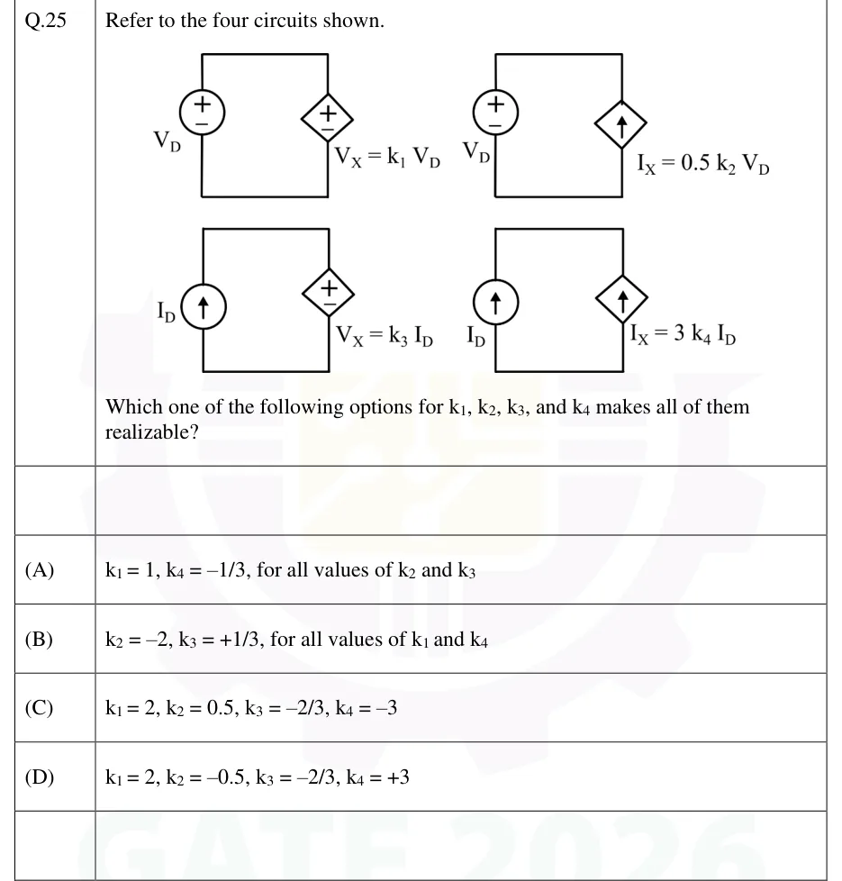
Refer to the four circuits shown.

[Figure: four two-element loops]

Which one of the following options for , , , and makes all of them realizable?

GATE 2026 EE question 25: Four separate circuits.Tap to open full size
Figure from the GATE 2026 EE paper. It is part of the question.
Figure description

Four separate circuits. Each is one closed loop with two elements, left and right, joined by a top wire and a bottom wire, so the two elements are in parallel (equivalently, in series around the single loop). (1) Top-left: on the left, an independent voltage source V_D (circle), + terminal at the top. On the right, a dependent voltage source (diamond), + terminal at the top, labelled V_X = k_1 V_D. (2) Top-right: on the left, an independent voltage source V_D (circle), + at the top. On the right, a dependent current source (diamond) with its arrow pointing up, labelled I_X = 0.5 k_2 V_D. (3) Bottom-left: on the left, an independent current source I_D (circle) with its arrow pointing up. On the right, a dependent voltage source (diamond), + at the top, labelled V_X = k_3 I_D. (4) Bottom-right: on the left, an independent current source I_D (circle) with its arrow pointing up. On the right, a dependent current source (diamond) with its arrow pointing up, labelled I_X = 3 k_4 I_D.

  1. (A)

    , , for all values of and

  2. (B)

    , , for all values of and

  3. (C)

    , , ,

  4. (D)

    , , ,

Answer and solution
GATE 2026 EE Q.25: answer and solution

GATE 2026 IN Q.40

GATE 2026 · INQ.40 · 2 marks · MCQ

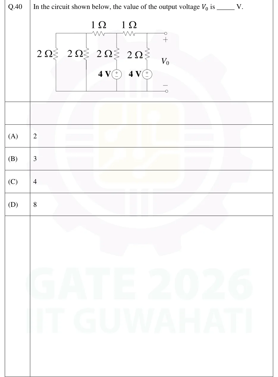
In the circuit shown below, the value of the output voltage is ______ V.

GATE 2026 IN question 40: A ladder network between a top rail and a bottom (reference) rail, drawn left to right.Tap to open full size
Figure from the GATE 2026 IN paper. It is part of the question.
Figure description

A ladder network between a top rail and a bottom (reference) rail, drawn left to right. The top rail runs from the far-left corner to a node A, then through a series 1 Ω resistor to node B, then through a second series 1 Ω resistor to node C, and from C by a plain wire to the output terminal marked +. The bottom rail is one plain wire that joins the foot of every vertical branch and ends at the output terminal marked −. Vertical branches, top rail to bottom rail, from left to right: (1) at the far left, a 2 Ω resistor (its top is joined to node A by plain wire); (2) at node A, a 2 Ω resistor; (3) at node B, a 2 Ω resistor in series with a 4 V DC source, + terminal upward (toward the resistor and node B), − terminal on the bottom rail; (4) at node C, a 2 Ω resistor in series with a 4 V DC source, + terminal upward, − terminal on the bottom rail. V_0 is the voltage from the + output terminal (node C) to the − output terminal (bottom rail).

  1. (A)

    2

  2. (B)

    3

  3. (C)

    4

  4. (D)

    8

Answer and solution
GATE 2026 IN Q.40: answer and solution

GATE 2025 EC Q.19

GATE 2025 · ECQ.19 · 1 mark · MCQ

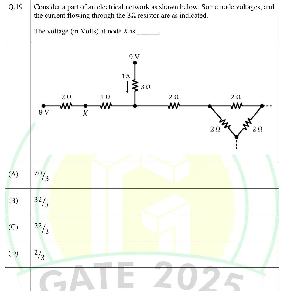
Consider a part of an electrical network as shown below. Some node voltages, and the current flowing through the resistor are as indicated.

The voltage (in Volts) at node is ______.

GATE 2025 EC question 19: A horizontal chain of resistors running left to right.Tap to open full size
Figure from the GATE 2025 EC paper. It is part of the question.
Figure description

A horizontal chain of resistors running left to right. Leftmost node is marked 8 V. A 2 Ω resistor joins it to node X. A 1 Ω resistor joins X to an unlabelled junction node (call it N). From N, a 3 Ω resistor goes straight up to a node marked 9 V. An arrow labelled 1A beside the 3 Ω resistor points downward, so 1 A flows through the 3 Ω resistor from the 9 V node down into N. From N, another 2 Ω resistor goes to the right and ends at the left corner of a triangle (delta) made of three 2 Ω resistors: a top 2 Ω between the left and right corners, a 2 Ω from the left corner down to the bottom corner, and a 2 Ω from the right corner down to the bottom corner. A dotted line runs right from the right corner and down from the bottom corner, showing that the network continues and is not drawn. Node X connects only to the 2 Ω and the 1 Ω resistors.

  1. (A)

  2. (B)

  3. (C)

  4. (D)

Answer and solution
GATE 2025 EC Q.19: answer and solution

GATE 2025 EE Q.18

GATE 2025 · EEQ.18 · 1 mark · MCQ

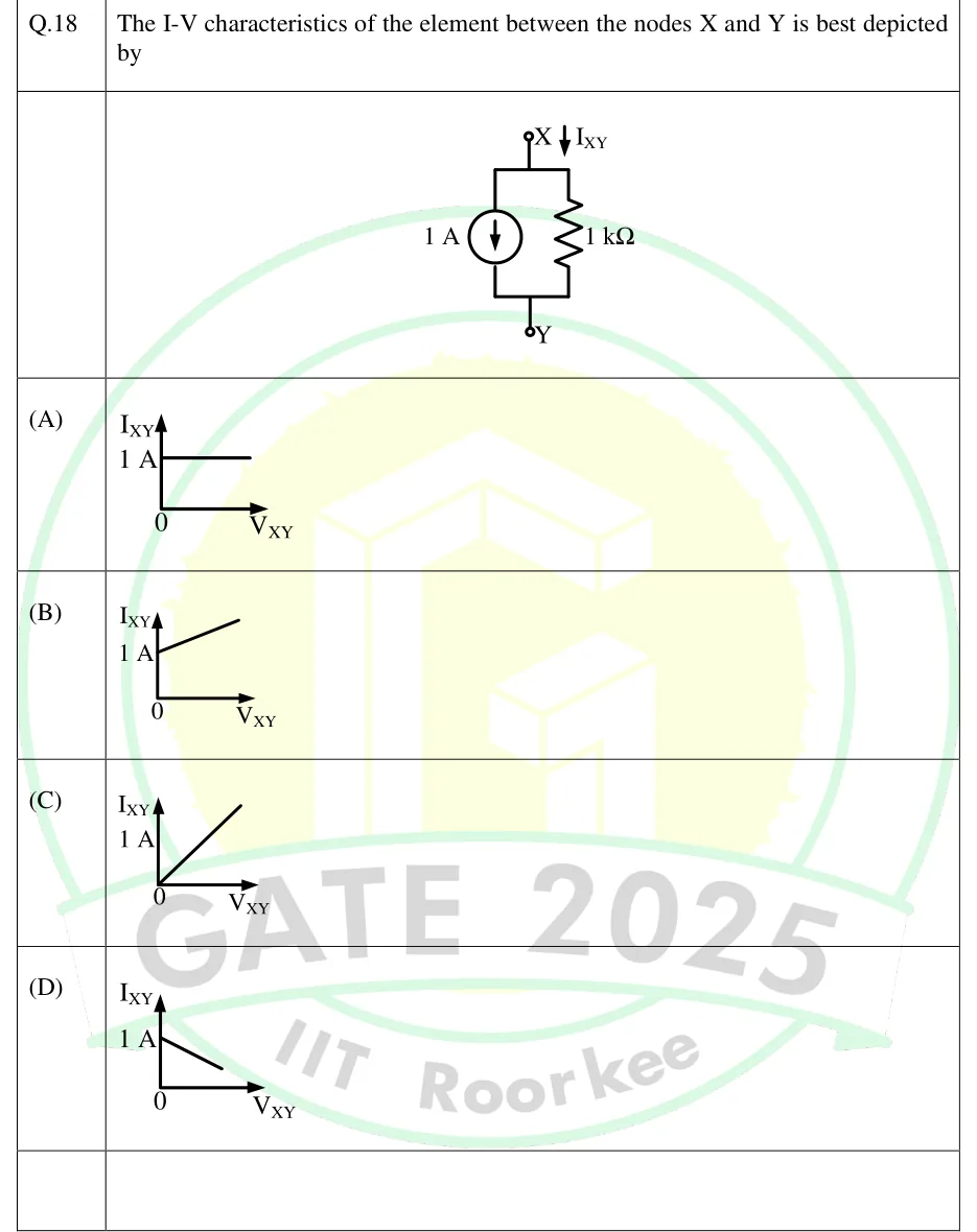
The I-V characteristics of the element between the nodes X and Y is best depicted by

GATE 2025 EE question 18: Two-terminal element between terminal X (top) and terminal Y (bottom).Tap to open full size
Figure from the GATE 2025 EE paper. It is part of the question.
Figure description

Two-terminal element between terminal X (top) and terminal Y (bottom). A current I_XY is marked by an arrow pointing downward at terminal X, i.e. entering the element at X. Terminal X connects to a top node; terminal Y connects to a bottom node. Between the top and bottom nodes, two branches are in parallel: on the left an independent current source of 1 A whose arrow points downward (driving current from the top node through the source to the bottom node); on the right a 1 kΩ resistor. Each option is a sketch of I_XY (vertical axis) against V_XY (horizontal axis), origin marked 0, with the level 1 A marked on the I_XY axis. (A) horizontal line at I_XY = 1 A, starting at V_XY = 0. (B) straight line starting at 1 A on the I_XY axis and rising with positive slope as V_XY increases. (C) straight line through the origin with positive slope. (D) straight line starting at 1 A on the I_XY axis and falling with negative slope as V_XY increases.

  1. (A)

    Figure — horizontal line at I_XY = 1 A for V_XY ≥ 0 (zero slope)

  2. (B)

    Figure — straight line with intercept 1 A on the I_XY axis and positive slope

  3. (C)

    Figure — straight line through the origin with positive slope

  4. (D)

    Figure — straight line with intercept 1 A on the I_XY axis and negative slope

Answer and solution
GATE 2025 EE Q.18: answer and solution

GATE 2024 EC Q.31

GATE 2024 · ECQ.31 · 1 mark · NAT

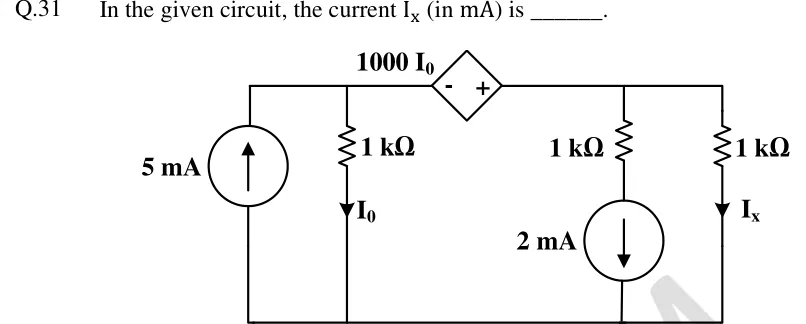
In the given circuit, the current (in mA) is ______.

GATE 2024 EC question 31: A multi-branch circuit with a common bottom (ground) rail and a top rail split into two nodes, A (left) and B (right).Tap to open full size
Figure from the GATE 2024 EC paper. It is part of the question.
Figure description

A multi-branch circuit with a common bottom (ground) rail and a top rail split into two nodes, A (left) and B (right). Left of node A: an independent 5 mA current source between ground and A, arrow pointing up (current pushed into A). Next, a 1 kΩ resistor from A down to ground, carrying current I_0 marked flowing downward. Node A connects to node B along the top rail through a dependent (diamond) voltage source of value 1000 I_0, with its − terminal on the left (node A) and + terminal on the right (node B), so V_B - V_A = 1000 I_0. From node B to ground there are two branches: (i) a 1 kΩ resistor in series with a 2 mA independent current source whose arrow points down (towards ground); (ii) a 1 kΩ resistor carrying current I_x marked flowing downward to ground.

Answer and solution
GATE 2024 EC Q.31: answer and solution

GATE 2024 EE Q.12

GATE 2024 · EEQ.12 · 1 mark · MCQ

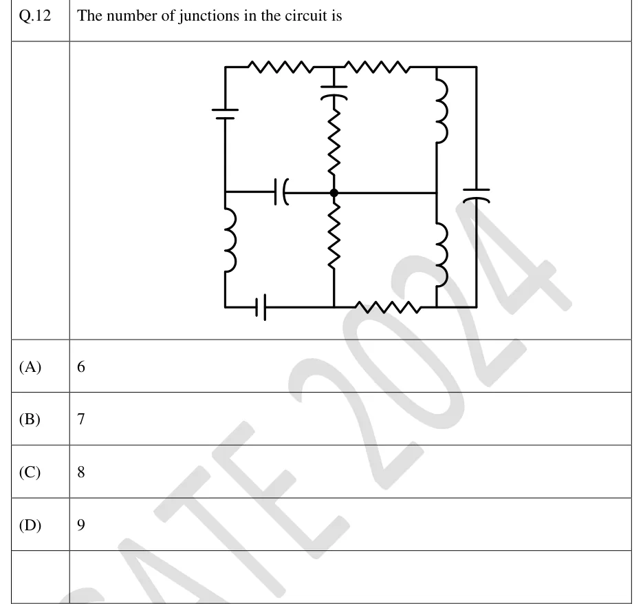
The number of junctions in the circuit is

GATE 2024 EE question 12: A rectangular grid network with three vertical lines (left, middle, right-inner) plus an outer right vertical line, and…Tap to open full size
Figure from the GATE 2024 EE paper. It is part of the question.
Figure description

A rectangular grid network with three vertical lines (left, middle, right-inner) plus an outer right vertical line, and three horizontal levels (top, middle, bottom). Label the points: top row A (left corner), B (middle), T (right-inner), T' (outer right corner); middle row D (left), O (centre, the only point drawn with a solid dot), E (right-inner); bottom row F (left corner), G (middle), H (right-inner), H' (outer right corner). Elements: A-B resistor; B-T resistor; T-T' plain wire; A-D (left side, upper half) DC voltage source (battery); D-F (left side, lower half) inductor; F-G (bottom, left half) battery; G-H resistor; H-H' plain wire; B-O (middle vertical, upper half) a capacitor just below B in series with a resistor; O-G (middle vertical, lower half) resistor; D-O horizontal capacitor; O-E plain wire; T-E (right-inner vertical, upper half) inductor; E-H (right-inner vertical, lower half) inductor; T'-H' (outer right vertical) capacitor. Source polarities are not needed for the question. Element values are not given.

  1. (A)

    6

  2. (B)

    7

  3. (C)

    8

  4. (D)

    9

Answer and solution
GATE 2024 EE Q.12: answer and solution

GATE 2024 EE Q.13

GATE 2024 · EEQ.13 · 1 mark · MCQ

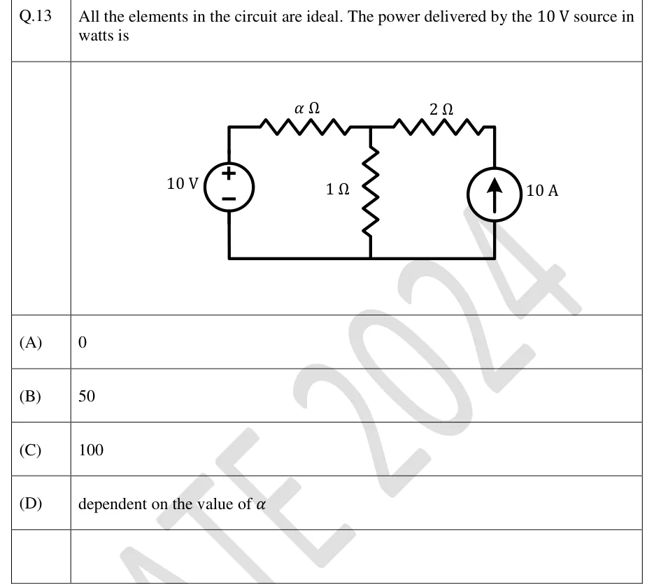
All the elements in the circuit are ideal. The power delivered by the source in watts is

GATE 2024 EE question 13: Single-loop-pair circuit with a common bottom (reference) wire.Tap to open full size
Figure from the GATE 2024 EE paper. It is part of the question.
Figure description

Single-loop-pair circuit with a common bottom (reference) wire. Left branch: an ideal 10 V voltage source, + terminal at the top, - terminal at the bottom wire. From the top of the voltage source, a resistor of α Ω runs horizontally to a top middle node (call it A). A 1 Ω resistor connects node A vertically down to the bottom wire. From node A, a 2 Ω resistor runs horizontally to the top right node. Right branch: an ideal 10 A current source between the bottom wire and the top right node, arrow pointing upward (current delivered from the bottom wire into the top right node, i.e. towards the 2 Ω resistor and node A). The bottom wire joins the bottoms of the voltage source, the 1 Ω resistor and the current source.

  1. (A)

    0

  2. (B)

    50

  3. (C)

    100

  4. (D)

    dependent on the value of

Answer and solution
GATE 2024 EE Q.13: answer and solution

GATE 2024 IN Q.51

GATE 2024 · INQ.51 · 2 marks · NAT

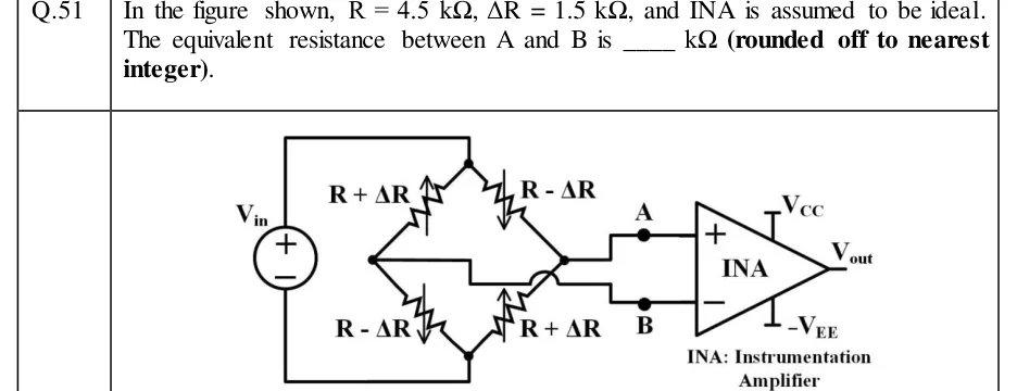
In the figure shown, , , and INA is assumed to be ideal. The equivalent resistance between A and B is ____ (rounded off to nearest integer).

GATE 2024 IN question 51: A four-arm resistive bridge drawn as a diamond, with top node T, bottom node Bot, left node L and right node Rt.Tap to open full size
Figure from the GATE 2024 IN paper. It is part of the question.
Figure description

A four-arm resistive bridge drawn as a diamond, with top node T, bottom node Bot, left node L and right node Rt. Every arm is a variable resistor (a zig-zag crossed by a vertical arrow, like a strain gauge). The arrow points up on the R + ΔR arms and down on the R - ΔR arms. Arm T-L: R + ΔR. Arm T-Rt: R - ΔR. Arm L-Bot: R - ΔR. Arm Rt-Bot: R + ΔR. A voltage source V_in on the left has its + terminal on top. Its + terminal is wired to the top node T and its - terminal to the bottom node Bot, so V_in is applied across T-Bot. The right node Rt is wired to terminal A. The left node L is wired to terminal B by a wire that runs right, steps down, and passes over the lead of the lower-right arm through a crossover arc (not a junction) before stepping down to B. A goes to the + (non-inverting) input of an instrumentation amplifier labelled INA, and B goes to its - (inverting) input. The INA has supply rails V_CC (top) and -V_EE (bottom) and output V_out. Caption: 'INA: Instrumentation Amplifier'.

Answer and solution
GATE 2024 IN Q.51: answer and solution

GATE 2024 IN Q.54

GATE 2024 · INQ.54 · 2 marks · NAT

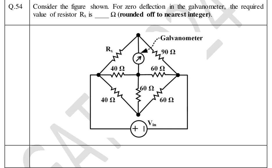
Consider the figure shown. For zero deflection in the galvanometer, the required value of resistor is ____ (rounded off to nearest integer).

GATE 2024 IN question 54: A diamond-shaped bridge with five nodes: top node T, left node L, centre node C, right node R and bottom node B.Tap to open full size
Figure from the GATE 2024 IN paper. It is part of the question.
Figure description

A diamond-shaped bridge with five nodes: top node T, left node L, centre node C, right node R and bottom node B. Upper-left arm: resistor R_x from L to T. Upper-right arm: 90 Ω from T to R. Galvanometer: vertical, from T down to C. Horizontal middle line: 40 Ω from L to C, then 60 Ω from C to R. Lower-left arm: 40 Ω from L to B. Centre vertical: 60 Ω from C to B. Lower-right arm: 60 Ω from R to B. Source V_in: a wire goes from L down the left side and along the bottom to a voltage source (+ terminal on the left) and on to the right side, rising to R. So V_in is connected between L (+) and R (−). Node B is not connected to the source directly.

Answer and solution
GATE 2024 IN Q.54: answer and solution

GATE 2023 EC Q.32

GATE 2023 · ECQ.32 · 1 mark · NAT

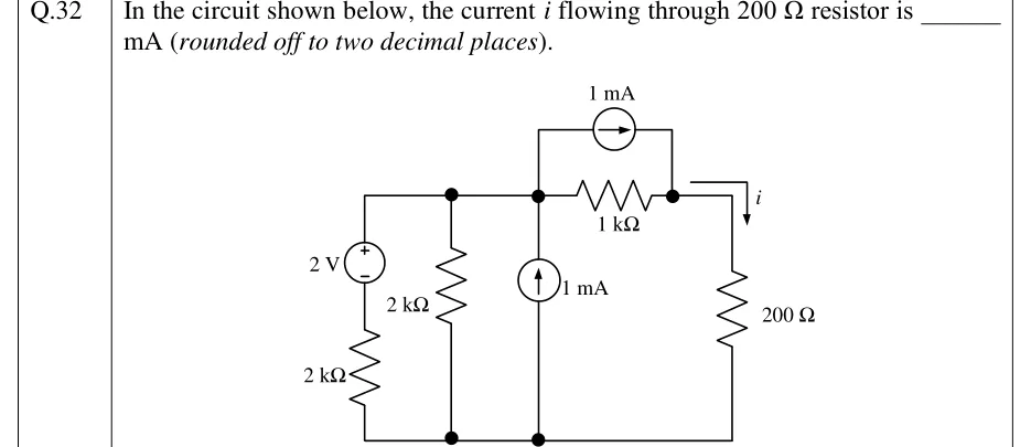
In the circuit shown below, the current flowing through resistor is ______ mA (rounded off to two decimal places).

GATE 2023 EC question 32: Three-node ladder with a common bottom (ground) rail.Tap to open full size
Figure from the GATE 2023 EC paper. It is part of the question.
Figure description

Three-node ladder with a common bottom (ground) rail. Top-left node A joins four branches. (1) Leftmost branch, from A down to ground: a 2 V independent voltage source with its + terminal at the top (towards A), in series with a 2 kΩ resistor below it that goes to the ground rail. (2) A 2 kΩ resistor from A straight down to ground. (3) An independent 1 mA current source from ground up to A (arrow pointing up, i.e. injecting 1 mA into A). (4) From A to the right: a 1 kΩ resistor to node B, with an independent 1 mA current source connected in parallel with this 1 kΩ, drawn above it, arrow pointing right (from A towards B). From node B a wire goes right and down through a 200 Ω resistor to the ground rail; the current i is marked on this wire flowing downward through the 200 Ω resistor.

Answer and solution
GATE 2023 EC Q.32: answer and solution

GATE 2023 EE Q.32

GATE 2023 · EEQ.32 · 1 mark · NAT

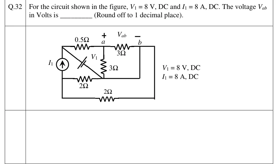
For the circuit shown in the figure, , DC and , DC. The voltage in Volts is ________ (Round off to 1 decimal place).

GATE 2023 EE question 32: A rectangular circuit with four distinct nodes.Tap to open full size
Figure from the GATE 2023 EE paper. It is part of the question.
Figure description

A rectangular circuit with four distinct nodes. Call the top-left corner P, the terminal on the top wire a, the terminal b, and the left-middle junction M. Top wire, left to right: P, a 0.5 Ω resistor, node a (marked +), a 3 Ω resistor, node b (marked −); V_ab is labelled across a (+) and b (−). From b the top wire carries on to the right-hand corner and down the right side to the bottom-right corner. Left side: the vertical wire from P down to M contains the current source I1, arrow pointing up, so it drives current from M up to P. Below M the left wire carries on to the bottom-left corner. A 2 Ω resistor on the bottom wire joins the bottom-left and bottom-right corners, so this 2 Ω sits between M and b. Middle horizontal wire: a 2 Ω resistor runs from M right to a junction N under node a. From N a plain wire runs right, then up a plain vertical wire to b, so N and b are the same node. A 3 Ω resistor hangs vertically from a down to N (= b). A diagonal from P down to N (= b) holds the DC voltage source V1, drawn as a battery. Its long plate (+) faces P and its short plate (−) faces N, so P is 8 V above b. The figure notes: V1 = 8 V, DC; I1 = 8 A, DC.

Answer and solution
GATE 2023 EE Q.32: answer and solution

GATE 2022 EC Q.13

GATE 2022 · ECQ.13 · 1 mark · MCQ

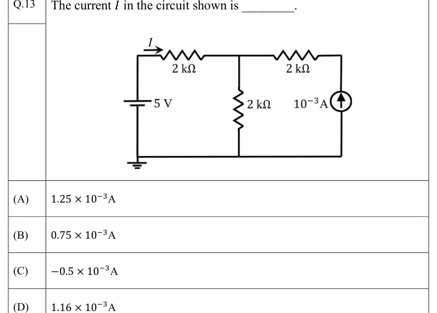
The current in the circuit shown is ________.

GATE 2022 EC question 13: Three-mesh ladder circuit with a common bottom (ground) wire.Tap to open full size
Figure from the GATE 2022 EC paper. It is part of the question.
Figure description

Three-mesh ladder circuit with a common bottom (ground) wire. Left branch: a 5 V DC source (battery symbol, longer plate i.e. positive terminal at the top) connected vertically between the top-left node and the bottom wire; the bottom wire is connected to ground (ground symbol under the left branch). Top wire: from the top-left node a 2 kΩ resistor runs right to a middle node A; an arrow labelled I above the left end of this resistor points to the right (current I flows from the source's positive terminal through the 2 kΩ toward node A). Middle branch: a 2 kΩ resistor from node A down to the bottom wire. From node A a second 2 kΩ resistor runs right along the top to the top-right corner. Right branch: an independent current source of 10^-3 A connected vertically between the bottom wire and the top-right corner, arrow pointing up (current delivered upward into the top-right node, i.e. toward node A through the right 2 kΩ).

  1. (A)

  2. (B)

  3. (C)

  4. (D)

Answer and solution
GATE 2022 EC Q.13: answer and solution

GATE 2022 EC Q.14

GATE 2022 · ECQ.14 · 1 mark · MCQ

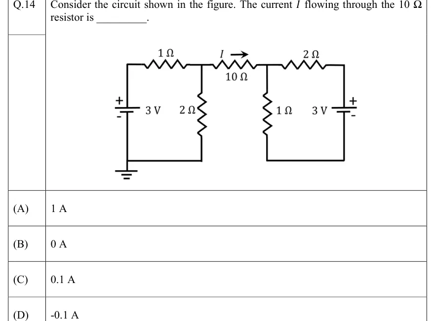
Consider the circuit shown in the figure. The current flowing through the resistor is ________.

GATE 2022 EC question 14: Two sub-circuits joined by a single 10 Ω resistor.Tap to open full size
Figure from the GATE 2022 EC paper. It is part of the question.
Figure description

Two sub-circuits joined by a single 10 Ω resistor. LEFT: a 3 V DC source drawn vertically, + terminal at top, - terminal at bottom; its bottom terminal sits on a bottom wire that is connected to a ground symbol. From the top (+) terminal a wire rises to a 1 Ω resistor in the top branch, running left to right to node A. From node A a 2 Ω resistor runs down to the same bottom (ground) wire, so the left loop is: 3 V source, 1 Ω, 2 Ω. RIGHT: node A connects through the 10 Ω resistor (horizontal, top branch) to node B; the current I is marked with an arrow pointing to the right (from A towards B) above the 10 Ω resistor. From node B a 1 Ω resistor runs down to a bottom wire on the right. From node B a 2 Ω resistor runs right along the top to the + (top) terminal of a second vertical 3 V DC source; its - (bottom) terminal connects to the right bottom wire, which returns to the bottom of the 1 Ω resistor. The right loop (2 Ω, 3 V source, 1 Ω) has its own bottom wire; it is NOT connected to the left bottom wire or to ground. The 10 Ω resistor is the only connection between the two loops.

  1. (A)

    1 A

  2. (B)

    0 A

  3. (C)

    0.1 A

  4. (D)

    -0.1 A

Answer and solution
GATE 2022 EC Q.14: answer and solution

GATE 2022 EE Q.55

GATE 2022 · EEQ.55 · 2 marks · NAT

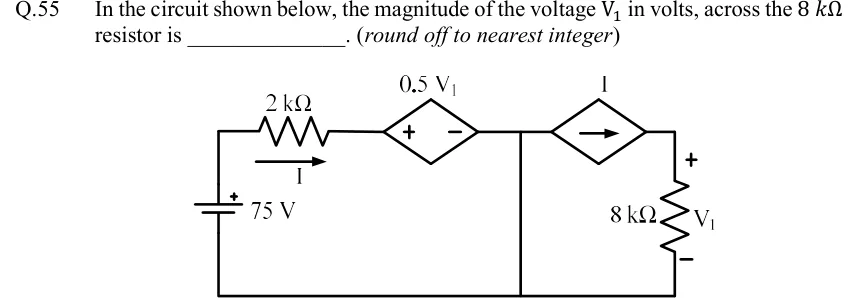
In the circuit shown below, the magnitude of the voltage in volts, across the resistor is ______. (round off to nearest integer)

GATE 2022 EE question 55: Two meshes that share a bottom ground wire.Tap to open full size
Figure from the GATE 2022 EE paper. It is part of the question.
Figure description

Two meshes that share a bottom ground wire. Left branch: an independent 75 V DC source on the left vertical side, + terminal at the top. From its top terminal a wire runs right through a 2 kΩ resistor. An arrow under the resistor labels current I, flowing left to right. Next comes a diamond-shaped dependent voltage source labelled 0.5 V1, + on its left terminal and − on its right terminal, which leads to a top-middle node. From that top-middle node a plain vertical wire (a short, with no element on it) runs straight down to the bottom wire. From the same top-middle node a diamond-shaped dependent current source labelled I, arrow pointing right, feeds the top-right node. From the top-right node an 8 kΩ resistor runs down to the bottom wire. The voltage across the 8 kΩ resistor is V1, + at the top and − at the bottom. The bottom wire joins the 75 V source's − terminal, the foot of the middle short and the foot of the 8 kΩ resistor.

Answer and solution
GATE 2022 EE Q.55: answer and solution

GATE 2020 EE Q.30

GATE 2020 · EEQ.30 · 2 marks · MCQ

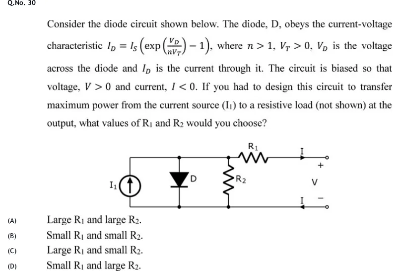
Consider the diode circuit shown below. The diode, D, obeys the current-voltage characteristic , where , , is the voltage across the diode and is the current through it. The circuit is biased so that voltage, and current, . If you had to design this circuit to transfer maximum power from the current source () to a resistive load (not shown) at the output, what values of and would you choose?

GATE 2020 EE question 30: Two horizontal rails, top and bottom.Tap to open full size
Figure from the GATE 2020 EE paper. It is part of the question.
Figure description

Two horizontal rails, top and bottom. From left to right, three elements are connected between the rails: (1) an independent current source I1 with its arrow pointing up, pushing current into the top rail; (2) diode D with the triangle pointing down, so the anode is on the top rail and the cathode is on the bottom rail; (3) resistor R2. Junction dots mark where D and R2 meet each rail. To the right of the R2 junction, resistor R1 sits in series in the top wire, which runs on to the upper output terminal (open circle). An arrow labelled I on the top wire, after R1, points right toward the upper terminal. An arrow labelled I on the bottom wire points left, from the lower terminal back into the circuit. The output voltage V is marked across the two terminals, + at the top and - at the bottom. The bottom rail runs straight to the lower terminal with no element in it.

  1. (A)

    Large and large .

  2. (B)

    Small and small .

  3. (C)

    Large and small .

  4. (D)

    Small and large .

Official answer

Official answer: DSource: Official answer key, GATE 2020 EE (IIT Delhi)

GATE 2020 EE Q.30: official answer

GATE 2020 EE Q.32

GATE 2020 · EEQ.32 · 2 marks · MCQ

A benchtop dc power supply acts as an ideal 4 A current source as long as its terminal voltage is below 10 V. Beyond this point, it begins to behave as an ideal 10 V voltage source for all load currents going down to 0 A. When connected to an ideal rheostat, find the load resistance value at which maximum power is transferred, and the corresponding load voltage and current.

  1. (A)

    Short, A, 10 V

  2. (B)

    Open, 4 A, 0 V

  3. (C)

    2.5 , 4 A, 10 V

  4. (D)

    2.5 , 4 A, 5 V

Answer and solution
See the question in the paper
GATE 2020 EE Q.32: answer and solution

GATE 2020 IN Q.4

GATE 2020 · INQ.4 · 1 mark · MCQ

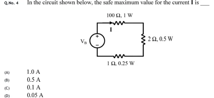
In the circuit shown below, the safe maximum value for the current is ____

GATE 2020 IN question 4: A single-loop series circuit.Tap to open full size
Figure from the GATE 2020 IN paper. It is part of the question.
Figure description

A single-loop series circuit. On the left is an independent voltage source labelled V_B, drawn as a circle with its + terminal at the top and its - terminal at the bottom. From the + terminal the top wire runs right through a resistor labelled '100 Ω, 1 W'. An arrow labelled I points to the right along this top branch, so I flows clockwise out of the + terminal. The top wire then goes down the right side through a resistor labelled '2 Ω, 0.5 W', and back along the bottom wire through a resistor labelled '1 Ω, 0.25 W' to the - terminal of V_B. All three resistors carry the same current I. There are no other elements or branches.

  1. (A)

    1.0 A

  2. (B)

    0.5 A

  3. (C)

    0.1 A

  4. (D)

    0.05 A

Answer and solution
GATE 2020 IN Q.4: answer and solution

GATE 2020 IN Q.30

GATE 2020 · INQ.30 · 2 marks · MCQ

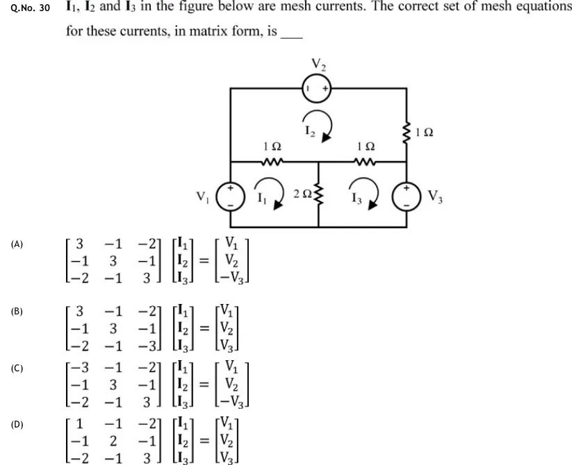
, and in the figure below are mesh currents. The correct set of mesh equations for these currents, in matrix form, is ___

GATE 2020 IN question 30: A planar circuit with three meshes, all mesh currents drawn clockwise.Tap to open full size
Figure from the GATE 2020 IN paper. It is part of the question.
Figure description

A planar circuit with three meshes, all mesh currents drawn clockwise. There are three nodes on a middle horizontal line: left node L, centre node M, right node R. There is a bottom rail and a top rail. Left vertical branch: source V_1 between the bottom rail (−) and node L (+, top). A plain wire runs from node L up to the top-left corner of the top rail. Top rail: source V_2 drawn horizontally, − terminal on the left, + terminal on the right, running from the top-left corner to the top-right corner. Right upper branch: a 1 Ω resistor from the top-right corner down to node R. Middle horizontal: a 1 Ω resistor between L and M, and a 1 Ω resistor between M and R. Centre vertical: a 2 Ω resistor from M down to the bottom rail. Right vertical branch: source V_3 between node R (+, top) and the bottom rail (−). Meshes: I_1 is the lower-left mesh (V_1, L–M 1 Ω, 2 Ω, bottom rail). I_2 is the top mesh (V_2, right 1 Ω, M–R 1 Ω, L–M 1 Ω, left wire). I_3 is the lower-right mesh (M–R 1 Ω, V_3, bottom rail, 2 Ω).

  1. (A)

  2. (B)

  3. (C)

  4. (D)

Answer and solution
GATE 2020 IN Q.30: answer and solution

GATE 2018 EC Q.53

GATE 2018 · ECQ.53 · 2 marks · NAT

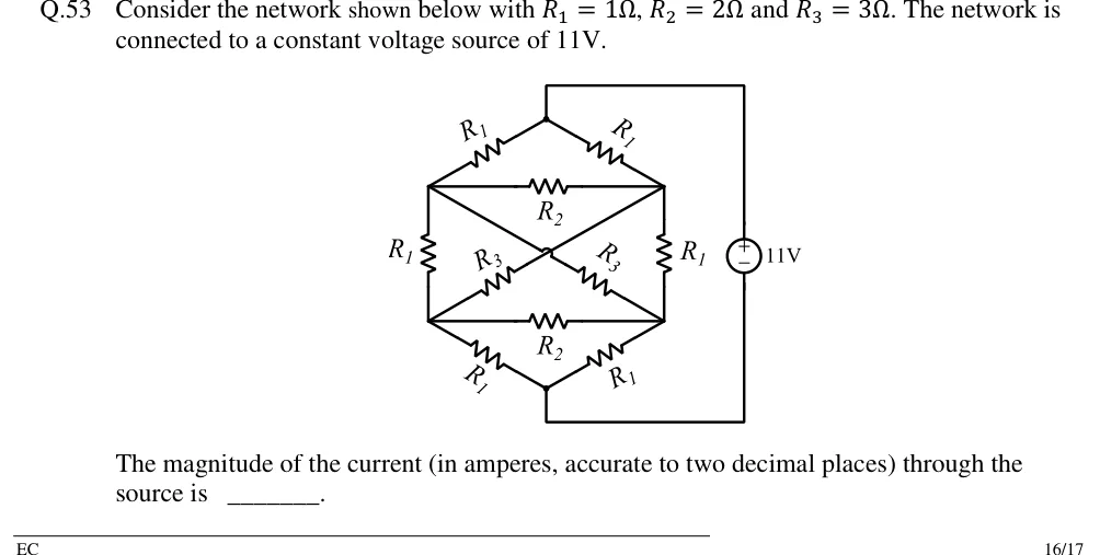
Consider the network shown below with , and . The network is connected to a constant voltage source of 11V.

The magnitude of the current (in amperes, accurate to two decimal places) through the source is ______.

GATE 2018 EC question 53: A hexagon-shaped resistor network with six nodes: top apex A, upper-left C, upper-right D, lower-left E, lower-right F…Tap to open full size
Figure from the GATE 2018 EC paper. It is part of the question.
Figure description

A hexagon-shaped resistor network with six nodes: top apex A, upper-left C, upper-right D, lower-left E, lower-right F, bottom apex B. Branches: A–C is R_1, A–D is R_1; C–D is a horizontal R_2; C–E is the left vertical R_1; D–F is the right vertical R_1; E–F is a horizontal R_2; E–B is R_1, F–B is R_1. Two diagonals: C to F with an R_3 drawn on the half nearer F, and D to E with an R_3 drawn on the half nearer E. The diagonals cross at the centre and no junction dot is drawn there (the answer is the same either way). An 11 V DC source stands to the right of the network: its + terminal is wired to the top apex A and its − terminal to the bottom apex B.

Answer and solution
GATE 2018 EC Q.53: answer and solution

GATE 2018 IN Q.32

GATE 2018 · INQ.32 · 2 marks · MCQ

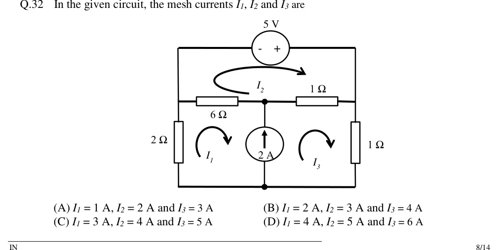
In the given circuit, the mesh currents , and are

GATE 2018 IN question 32: A planar circuit with three meshes.Tap to open full size
Figure from the GATE 2018 IN paper. It is part of the question.
Figure description

A planar circuit with three meshes. Outer rectangle: the top wire runs from the top-left corner to the top-right corner through a 5 V independent voltage source, with its − terminal on the left and + on the right. Below the top wire is a middle horizontal branch joining left node L, middle node M and right node R: a 6 Ω resistor between L and M, and a 1 Ω resistor between M and R. The top-left corner is joined to L by a plain wire, and the top-right corner is joined to R by a plain wire. Below L, a 2 Ω resistor runs vertically from L to the bottom wire. Below R, a 1 Ω resistor runs vertically from R to the bottom wire. From M, a 2 A independent current source runs vertically down to bottom node B, with its arrow pointing up (from B towards M). The bottom wire joins the bottom of the 2 Ω resistor, B and the bottom of the right 1 Ω resistor. Mesh currents, all clockwise: I_2 in the top mesh (5 V source, 1 Ω, 6 Ω); I_1 in the lower-left mesh (2 Ω, 6 Ω, 2 A source); I_3 in the lower-right mesh (2 A source, horizontal 1 Ω, vertical 1 Ω).

  1. (A)

    A, A and A

  2. (B)

    A, A and A

  3. (C)

    A, A and A

  4. (D)

    A, A and A

Answer and solution
GATE 2018 IN Q.32: answer and solution

PRACTICE

5 questions to test yourself

PRACTICE 11 mark · NAT

A , 1 W resistor and a , 1 W resistor are connected in series across a DC supply. The largest supply voltage (in V) that can be applied without exceeding the power rating of either resistor is ______.

Answer and solution

Answer: (accepted range )

  1. Safe currents from : A for the 100 Ω resistor and A for the 400 Ω resistor.

  2. In series both resistors carry the same current, so the string is limited to 0.05 A: the 400 Ω resistor reaches 1 W first.

  3. V. The total dissipation is then only 1.25 W, not 2 W.

PRACTICE 22 marks · NAT

A circuit has nodes 1 and 2 and a reference node 0. A 5 A independent current source drives current from node 0 into node 1. Resistors: from node 1 to 0, from node 1 to node 2, and from node 2 to 0. A voltage-controlled current source drives a current of amperes ( in volts) from node 0 into node 2, where is the voltage across the resistor between nodes 1 and 2. The power delivered by the dependent source (in W) is ______.

Answer and solution

Answer: (accepted range )

  1. KCL at node 1: , which gives .

  2. KCL at node 2 (current leaving through resistors = current injected): , which gives .

  3. Solving: V and V, so V and the dependent source current is 2 A.

  4. The source pushes 2 A from node 0 (0 V) into node 2 (8 V), so the current leaves it at its higher-potential terminal. It delivers W.

  5. Check: the sources deliver W, and the resistors absorb W.

PRACTICE 32 marks · MCQ

A circuit has nodes a, b, c and a reference node 0. An independent 20 V source is connected from 0 to a (+ at a). Resistors: between a and b, between b and 0, and between b and c. A current-controlled voltage source of value volts ( in A) is connected between c (+) and 0 (−), where is the current in the resistor from a to b. Using the passive sign convention, the power absorbed by the controlled source is

  1. (A)

    W

  2. (B)

    W

  3. (C)

    W

  4. (D)

    W

Answer and solution

Answer: (B)

  1. Draw the 20 V source as the left leg, the 2 Ω as the middle leg and the controlled source as the right leg. Take clockwise mesh currents (left) and (right). Then , and the 2 Ω carries downward.

  2. Mesh 1: , i.e. .

  3. Mesh 2: going b → c and then down through the source from + to − is a drop of , so , i.e. and .

  4. Then , so A and A. The source voltage is V.

  5. The current in the source branch, taken downward from + (c) to − (0), is A: 2 A actually flows out of the + terminal. Power absorbed W, i.e. the source delivers 32 W.

  6. Check by nodal analysis: V and V. KCL at b, , gives V, so A (consistent). The sources deliver W and the resistors absorb W.

PRACTICE 42 marks · MSQ

A battery with EMF 12 V and internal resistance is modelled as an ideal 12 V source in series with . Which of the following is/are correct?

  1. (A)

    The maximum power it can deliver to a resistive load is 72 W, obtained with a load.

  2. (B)

    With a load, the efficiency (load power ÷ power generated by the EMF) is 75%.

  3. (C)

    With a load, the terminal voltage is 10 V.

  4. (D)

    While an external charger drives 4 A into its + terminal, its terminal voltage is 14 V.

Answer and solution

Answer: (A), (B), (D)

  1. Maximum power occurs at : W. A is correct.

  2. With : . B is correct.

  3. The current is A, so the terminal voltage is V, not 10 V. C is wrong.

  4. While charging, current enters the + terminal, so V. D is correct.

PRACTICE 51 mark · MSQ

A star network has arms , and , connected from terminals a, b, c to a common internal node. It is replaced by its equivalent delta (, , ). Which of the following is/are correct?

  1. (A)

  2. (B)

  3. (C)

  4. (D)

    The resistance measured between a and b of the delta, with c left open, is

Answer and solution

Answer: (A), (C), (D)

  1. .

  2. ; ; . So A and C are correct and B is wrong.

  3. Between a and b of the delta with c open: . This equals in the star, as the equivalence requires, so D is correct.

OFFICIAL GATE 2027 SYLLABUS WORDING

Copied from the GATE 2027 syllabus; see all 2027 syllabi.

GATE EC

Node and mesh analysis … wye-delta transformation

GATE EE

Network Elements: Ideal voltage and current sources, dependent sources, R, L, C, M elements; Network solution methods: KCL, KVL, Node and Mesh analysis … star-delta transformation

GATE IN

Independent, dependent, ideal and practical sources; V-I characteristics of practical current and voltage sources, battery, solar cell, resistor, inductor, coupled inductor, capacitor … power and energy consumption, power rating of components, efficiency and losses. Kirchhoff’s laws, mesh and nodal analysis, star-delta transformation

Preparing in Kolkata? IAE Academy's course for GATE ECE, GATE EE or GATE IN.