IAE Academy

GATE EC · EE · IN

Network theorems

Network theorems let you replace all or part of a linear circuit with something simpler. Superposition splits the problem source by source, Thevenin and Norton reduce a network to one source and one impedance, and maximum power transfer then gives the best load in one line. Reciprocity, Millman, Miller, substitution and compensation are further shortcuts, and Tellegen's theorem is a power balance that holds for any lumped network. Common mistakes come from ignoring a theorem's conditions: switching off a dependent source, adding powers, using for a resistive AC load, or applying reciprocity to a network that contains controlled sources.

16 previous-year questions · 16 solved · 5 practice questions

Linearity and superposition

A circuit element is linear if its voltage–current relation satisfies two rules. Homogeneity: scaling the cause scales the effect by the same factor. Additivity: the effect of a sum of causes is the sum of the separate effects. Resistors, inductors, capacitors and coupled coils with constant values are linear, and so are linear dependent sources (output proportional to one voltage or current). A circuit built only from linear elements and independent sources is a linear circuit. In a resistive circuit, and in AC steady state at a single frequency, every voltage and current is a weighted sum of the independent source values. In a transient problem, the initial capacitor voltages and inductor currents act as extra sources.

LINEARITY (SUPERPOSITION)

= the independent source values; = any branch voltage or current. This holds for resistive circuits, and for AC steady state at one frequency, where and are phasors and the are complex numbers fixed by the circuit and the frequency. Dependent sources belong to the circuit and are never among the .

Superposition, step by step

  1. Keep one independent source active. Set every other independent source to zero: an ideal voltage source becomes a short circuit and an ideal current source becomes an open circuit. Any internal resistance of a source stays in place.

  2. Leave every dependent source in the circuit, still controlled by its own voltage or current. Dependent sources are never switched off.

  3. Find the required voltage or current, using the same reference direction in every sub-circuit.

  4. Repeat for each independent source (or for any convenient group of sources).

  5. Add the partial responses algebraically. If the sources have different frequencies, add them as time functions. Compute power from the total voltage or current; the one exception, average power from components at distinct frequencies, is covered below.

Linearity gives two more shortcuts. If every independent source is multiplied by , every response is multiplied by . This is the basis of the unit-output method for ladders with one source: assume V or A at the far end, work back to the source, then scale. And if a response has been measured at as many independent source settings as there are unknown coefficients, the can be found without ever seeing the circuit.

EXAM TIP

Black-box linearity. A linear circuit has a voltage source and a current source , so any response is . Suppose V, A gives V, and V, A gives V. Then and , so and . If the box also holds a fixed internal source that is never varied, add a constant term: . You then need three independent measurements.

EXAM TIP

Power does not superpose. Suppose one source alone drives A through a resistor and the other alone drives A in the same direction. Together they drive A, so W, not W. The missing part is the cross term . Superpose currents and voltages first, then compute power.

POWER AND RMS VALUE WITH COMPONENTS AT DIFFERENT FREQUENCIES

= DC component; = rms value of the component at frequency , with all the non-zero and distinct. Here average powers do add, because the cross terms average to zero over time. Two components at the same frequency do not: combine them as phasors first. Example: A gives A.

EXAM TIP

Sources at different frequencies (including DC). Solve each frequency in its own phasor circuit. For the DC source in steady state, an inductor is a short and a capacitor is an open. Convert each answer back to a time function, then add. Never add phasors that belong to different frequencies.

Thevenin and Norton equivalents

Seen from its terminals a–b, a linear two-terminal network behaves like one voltage source in series with an impedance (Thevenin), with the terminal of towards a. Equally, it behaves like one current source in parallel with the same impedance (Norton), with the arrow of pointing towards a. Only the network being replaced has to be linear; the load across a–b can be nonlinear, provided nothing couples the two sides except the two terminals (see the tip below). In AC, and belong to one frequency; sources at several frequencies need a separate equivalent at each frequency.

is the open-circuit voltage . is the short-circuit current , taken as flowing from a to b through the short. With these reference directions , and source transformation converts one form into the other. For resistive DC circuits, write for .

THEVENIN–NORTON RELATIONS

with a–b open; flows from a to b through a short across a–b. The ratio cannot be used when both are zero. That is always the case for a network with no independent source, and it can also happen when the sources inside produce nothing at a–b (a balanced bridge, for example). Then use the test-source method.

SOURCE TRANSFORMATION

The arrow of points towards the terminal on the side of . The two forms are equivalent only as seen from the terminals: the current and power inside differ. A dependent source can be transformed the same way, provided its controlling variable is not inside the being moved. An ideal voltage source () or an ideal current source () cannot be transformed.

TEST-SOURCE METHOD

Short the independent voltage sources, open the independent current sources, and leave every dependent source active. Apply across a–b ( at a) and find the current entering terminal a from the test source (or inject into a and find ). This works whenever the equivalent exists, and it is the method to use when the network has no independent source.

Three ways to find the Thevenin resistance

  1. Only independent sources in the network: switch them off and reduce by series–parallel combination.

  2. Any linear network: compute and separately and take . This works with dependent sources, provided and are not both zero.

  3. Dependent sources present (always valid): switch off the independent sources only and apply a test source. A network with only dependent sources and resistors has and , and its equivalent is just .

WORKED EXAMPLE · EXAMPLE 1: THEVENIN EQUIVALENT WITH A DEPENDENT SOURCE

A V independent source (positive terminal up, negative terminal on the reference node b) is connected through a resistor to node a. Let be the current in the resistor, flowing from the source towards a. Two elements connect node a to b: a resistor, and a current-controlled current source of value that pushes current from b into node a. A variable load is connected across a–b. Find the Thevenin equivalent at a–b, the value of for maximum power, and that maximum power.

Solution
  1. Open-circuit voltage. With a–b open, KCL at a gives (current in) = (current out through ): , where .

  2. So , which gives and V. Hence V.

  3. Short-circuit current. With a–b shorted, and the resistor carries nothing. A, and the dependent source adds A. So A, flowing from a to b through the short.

  4. , and the Norton current is A.

  5. Check with a test source. Short the V source and apply at a, with entering a. Now . KCL at a: , so . That gives , as before.

  6. The naive answer , found by deleting the dependent source, is wrong.

  7. Maximum power: and W.

Answer: V, ( A); maximum power at , W.

EXAM TIP

A dependent source can make smaller or larger than the passive resistors suggest, and even zero or negative. A negative is a correct result, not an arithmetic slip, but the maximum power formulas below then do not apply: they need . If , the network has no Norton equivalent; if is infinite, it has no Thevenin equivalent.

EXAM TIP

Only cut the circuit where each dependent source and its controlling voltage or current are on the same side, and where no mutual inductance links the two sides. If the controlling variable lies in the load, first rewrite it in terms of the terminal voltage or current.

Maximum power transfer

Suppose the source network is fixed, so its Thevenin equivalent is fixed, and the load can vary. The load power is zero at and tends to zero as , so it peaks somewhere in between. For , setting gives . Throughout this section, power means power absorbed by the load (passive sign convention). For AC, all phasors are rms values.

MAXIMUM POWER TRANSFER, RESISTIVE LOAD

is fixed and varies. If the network has dependent sources, use the found with them active.

LOAD POWER FOR ANY LOAD RESISTANCE

rises for and falls for . So if is restricted to a range that excludes , the best choice is the allowed value nearest .

EFFICIENCY OF THE THEVENIN EQUIVALENT

This is the efficiency of the Thevenin equivalent circuit only. The power drawn from the sources inside the original network is different, so the real efficiency at matching is generally not 50%.

EXAM TIP

Maximum power transfer is not maximum efficiency. As the efficiency approaches 100%, but the load power falls towards zero. The reverse problem has a different answer: if is fixed and the source resistance can be chosen, the load power is largest when the source resistance is , not when it equals .

For AC, the source is the rms phasor behind , and the load is . The average power in the load is . Only absorbs average power. Which load is best depends on which parts of are free to vary.

AC MAXIMUM POWER TRANSFER, CONJUGATE MATCH

Use this when both and are free (and ). The reactances cancel, so the loop is resonant. is an rms value; if the phasor is a peak value , then .

AC SOURCE, PURELY RESISTIVE LOAD

Use this when the load must be a pure resistor (). Choosing here is a common error.

FIXED LOAD REACTANCE, VARIABLE LOAD RESISTANCE

is fixed and varies; is evaluated at that . The pure-resistor case is , which gives back .

FIXED LOAD ANGLE, VARIABLE MAGNITUDE

Use this for a load whose angle is fixed (a fixed power factor) and whose magnitude alone varies; is the angle of . Setting gives back the pure-resistor result, and gives back the conjugate match.

Which AC load gives maximum power

What the load can vary

Condition for maximum power

Maximum power (rms )

and freely

only, pure resistor

only, fixed

at that

only, fixed

only, angle fixed

WORKED EXAMPLE · EXAMPLE 2: BEST AC LOAD, FREE AND RESISTIVE

At the operating frequency, the Thevenin equivalent of a network at its load terminals is V (rms) in series with . Find the maximum average power the load can absorb (a) if the load impedance is unrestricted, and (b) if the load must be a pure resistor. (c) Show that a resistor does worse than the answer to (b).

Solution
  1. (a) Conjugate match: . The loop impedance is , so A rms and W. The formula gives the same result.

  2. (b) Pure resistor: . The loop impedance is , so and W.

  3. Shortcut check for (b): W.

  4. (c) With : , so W, which is less than W.

Answer: (a) W with ; (b) W with ; (c) W with .

Reciprocity, Tellegen and Millman

A network is reciprocal if the ratio of a response to its excitation stays the same when the excitation and the response swap places. Only two swaps are guaranteed. The first is an ideal voltage source with the short-circuit current in another branch (an ideal ammeter). The second is an ideal current source with the open-circuit voltage across another pair of terminals (an ideal voltmeter). When a voltage source moves, the branch it leaves is short-circuited. When a current source moves, the branch it leaves is left open.

The two forms of reciprocity

Excitation

Response

Quantity unchanged by the swap

Ideal voltage source in branch 1

Short-circuit current in branch 2

Transfer admittance

Ideal current source at port 1

Open-circuit voltage at port 2

Transfer impedance

Conditions for reciprocity

  1. All elements linear and time-invariant.

  2. All elements bilateral. Resistors, inductors, capacitors, coupled coils () and ideal transformers qualify; diodes do not.

  3. No dependent sources. A controlled source, a transistor model or an op-amp generally makes the network non-reciprocal.

  4. A single independent source, with all initial conditions zero.

  5. The ratio must pair a voltage source with a short-circuit current, or a current source with an open-circuit voltage.

RECIPROCITY CONDITIONS FOR A TWO-PORT

Convention: and both flow INTO their ports, and ABCD is defined by , . Where the parameter sets exist, any one condition implies the others. Symmetry (, ) is a separate, stronger property.

EXAM TIP

In a reciprocal network, suppose V at port 1 drives A through a short at port 2. Then V at port 2 drives A through a short at port 1: reciprocity plus linearity. Voltage ratios do not swap like this. with port 2 open equals , while the reverse ratio equals . The two are equal only if the network is also symmetric.

Tellegen's theorem uses only KCL and KVL on the network graph. It therefore holds for any lumped network: linear or nonlinear, time-varying or not, with any sources. Take associated reference directions (passive sign convention) on every branch, so that is the power absorbed by branch .

TELLEGEN'S THEOREM

The sums run over all branches. The first form is conservation of power: the power delivered by the sources equals the power absorbed by everything else. The second form pairs voltages from one network with currents from another that has the same graph and the same reference directions. It also holds for one network at two different instants.

Millman's theorem combines several parallel branches between two nodes a and b. Each branch is a voltage source (positive terminal towards a) in series with an impedance , with admittance . The theorem is nodal analysis at node a written in one line. The result is the Thevenin equivalent of the whole parallel group.

MILLMAN'S THEOREM

= ideal current sources between the two nodes, directed into a; they add nothing to the denominator. A passive branch enters with . An ideal voltage source with cannot be included, because it fixes directly.

Miller, substitution and compensation theorems

Miller's theorem removes an impedance that bridges two nodes 1 and 2, typically the input and output of an amplifier. It requires the node voltages, measured from ground, to satisfy . The current leaving node 1 through is . An impedance from node 1 to ground would draw exactly this current. The same argument at node 2 gives the second impedance.

MILLER'S THEOREM

is removed and replaced by from node 1 to ground and from node 2 to ground. must be the gain with connected. For , is negative; for (a follower), is negative.

MILLER CAPACITANCE

This is the capacitor version (impedance ). For an inverting stage, with . Then is large (the Miller effect), and when . A bridging resistor becomes at the input.

EXAM TIP

The Miller split reproduces the node voltages only for the that holds with in place. It therefore cannot be used to find the output impedance of the stage. Using a gain computed without connected is an approximation.

Substitution theorem. Suppose a branch carries current and has voltage across it. It can be replaced by an independent voltage source (same polarity) or an independent current source (same direction), and every other voltage and current stays the same. The only condition is that the new network still has a unique solution. This theorem justifies treating a known node voltage or branch current as a source when a circuit is analysed in pieces.

Compensation theorem. In a linear network, let one branch with impedance carry current , and let its impedance change to . Switch off all independent sources and insert a single voltage source in series with the modified branch, with its polarity opposing . The currents this source produces are exactly the changes in every branch current.

COMPENSATION THEOREM

= original branch current. = impedance seen by the branch looking into the rest of the network, with independent sources off. The minus sign says that increasing the impedance reduces the branch current. A typical use is the error caused by inserting an ammeter of resistance .

Choosing a theorem and checking its conditions

Where each theorem applies

Theorem

Applies to

Watch out for

Superposition

Linear circuits with any number of independent sources; dependent sources allowed

Dependent sources stay on; power is not superposable; different frequencies add in the time domain

Thevenin / Norton

A linear network seen from two terminals; the load may be nonlinear

A dependent source and its controlling variable on the same side of the cut, and no mutual inductance across it; direction from a to b

Maximum power transfer

Fixed source network with , variable load

Conjugate match only if is free; pure resistor needs ; 50% efficiency holds only for the Thevenin model

Reciprocity

Linear, bilateral, time-invariant networks with no dependent sources and a single source

Only the voltage source with short-circuit current and current source with open-circuit voltage swaps

Tellegen

Any lumped network, linear or not

Associated reference directions on every branch; the two-network form needs the same graph

Millman

Parallel branches of sources with series impedances

A branch that is an ideal voltage source () cannot enter the formula

Miller

An impedance between two nodes with a known ratio

taken with connected; not valid for output impedance

Substitution

Any network with a unique solution

The replacement source must equal the branch's actual voltage or current

Compensation

A linear network in which one branch impedance changes

The changes are found with independent sources off and the modified impedance in place

EXAM TIP

Quick self-checks. With a–b open, the Thevenin model should give back ; with a–b shorted, it should give back . At a matched resistive load the load voltage is and the load current is : solving the original circuit with connected should give the same values. If it does not, recheck .

PREVIOUS-YEAR QUESTIONS

16 questions from the EC, EE and IN papers

Try each question first, then open the answer. We placed each question under a topic ourselves; the exam paper does not label topics.

See these papers in full: GATE ECE 2024 · GATE ECE 2022 · GATE ECE 2020 · GATE EE 2026 · GATE EE 2023 · GATE EE 2020 · GATE IN 2025 · GATE IN 2023 · GATE IN 2022 · GATE IN 2020 · GATE IN 2018

GATE 2026 EE Q.24

GATE 2026 · EEQ.24 · 1 mark · MCQ

For the circuit shown, which one of the following options correctly identifies the Thevenin's equivalent parameters between nodes Y and Z?
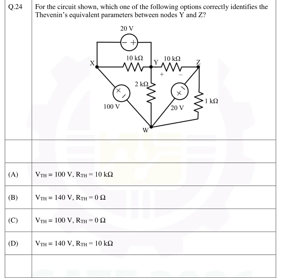
GATE 2026 EE question 24: Four nodes: X (left), Y (top middle), Z (top right), W (bottom middle).Tap to open full size
Figure from the GATE 2026 EE paper. It is part of the question.
Figure description

Four nodes: X (left), Y (top middle), Z (top right), W (bottom middle). Branches: (1) a 20 V independent voltage source on a top wire running from X up, across and down to Y, with its '-' terminal on the X side and '+' terminal on the Y side; (2) a 10 kOhm resistor directly between X and Y, in parallel with that 20 V source; (3) a 10 kOhm resistor between Y and Z, marked '+' at the Y end and '-' at the Z end; (4) a 100 V independent voltage source on the diagonal from X down to W, '+' toward X and '-' toward W; (5) a 2 kOhm resistor vertically between Y and W; (6) a 20 V independent voltage source on the diagonal from Z down to W, '-' toward Z and '+' toward W; (7) a 1 kOhm resistor between Z and W (right side). The Thevenin equivalent is asked between Y and Z.

  1. (A)

    ,

  2. (B)

    ,

  3. (C)

    ,

  4. (D)

    ,

Answer and solution
GATE 2026 EE Q.24: answer and solution

GATE 2026 EE Q.44

GATE 2026 · EEQ.44 · 2 marks · MCQ

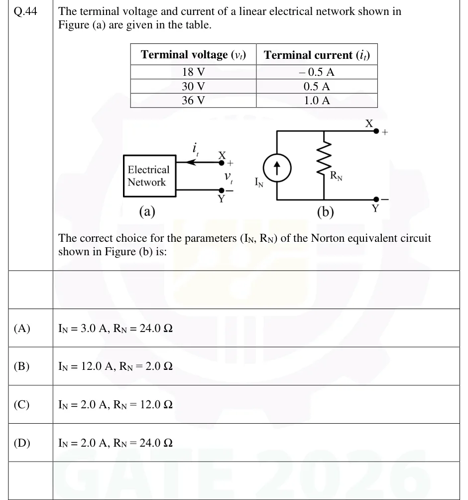
The terminal voltage and current of a linear electrical network shown in Figure (a) are given in the table.

| Terminal voltage () | Terminal current () |
|---|---|
| 18 V | A |
| 30 V | 0.5 A |
| 36 V | 1.0 A |

The correct choice for the parameters (, ) of the Norton equivalent circuit shown in Figure (b) is:

GATE 2026 EE question 44: Figure (a): a box labelled 'Electrical Network' with two terminals brought out to the right.Tap to open full size
Figure from the GATE 2026 EE paper. It is part of the question.
Figure description

Figure (a): a box labelled 'Electrical Network' with two terminals brought out to the right. The top terminal is X, marked +, and the bottom terminal is Y, marked −. The terminal voltage v_t is taken across X–Y (+ at X). The terminal current i_t is drawn on the top wire with its arrow pointing left, i.e. flowing from terminal X INTO the network. Figure (b): the Norton equivalent. An independent current source I_N with its arrow pointing upward (toward the top wire) is connected in parallel with a resistor R_N. The top wire goes to terminal X (+) and the bottom wire goes to terminal Y (−).

  1. (A)

    ,

  2. (B)

    ,

  3. (C)

    ,

  4. (D)

    ,

Answer and solution
GATE 2026 EE Q.44: answer and solution

GATE 2026 EE Q.60

GATE 2026 · EEQ.60 · 2 marks · NAT

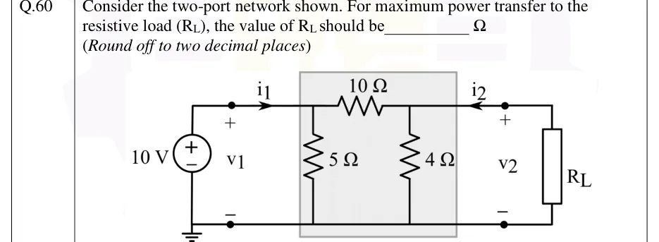
Consider the two-port network shown. For maximum power transfer to the resistive load (), the value of should be ________ (Round off to two decimal places)

GATE 2026 EE question 60: An ideal 10 V DC voltage source, + terminal on top, drives port 1;Tap to open full size
Figure from the GATE 2026 EE paper. It is part of the question.
Figure description

An ideal 10 V DC voltage source, + terminal on top, drives port 1; its bottom (negative) terminal is on the grounded bottom rail. Port-1 terminals are marked v_1 (+ on top, − at the bottom), and current i_1 flows right into the top terminal of the two-port. The two-port (shaded box) is a pi network: a 5 Ω shunt resistor from the top-left node to the bottom rail, a 10 Ω series resistor along the top from the left top node to the right top node, and a 4 Ω shunt resistor from the top-right node to the bottom rail. Port 2 is on the right: voltage v_2 (+ on top, − at the bottom), with current i_2 flowing left into the top terminal of the two-port. A resistive load R_L is connected across port 2. The bottom rail is common to both ports and grounded at the source side.

Answer and solution
GATE 2026 EE Q.60: answer and solution

GATE 2025 IN Q.45

GATE 2025 · INQ.45 · 2 marks · MCQ

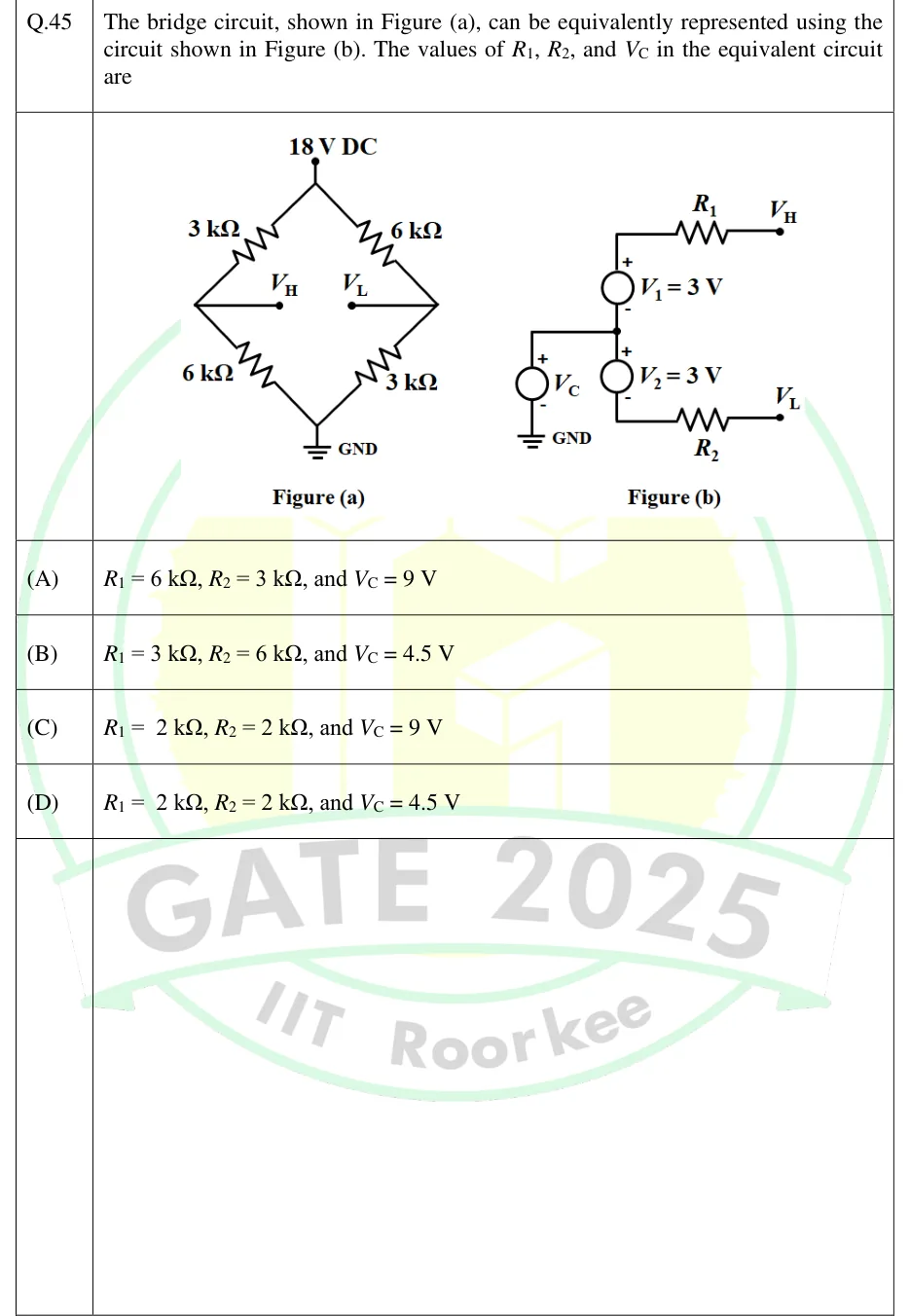
The bridge circuit, shown in Figure (a), can be equivalently represented using the circuit shown in Figure (b). The values of , , and in the equivalent circuit are

GATE 2025 IN question 45: Figure (a): A diamond-shaped bridge.Tap to open full size
Figure from the GATE 2025 IN paper. It is part of the question.
Figure description

Figure (a): A diamond-shaped bridge. The top vertex connects to an 18 V DC supply and the bottom vertex to GND. Upper-left arm (top to left node): 3 kΩ. Lower-left arm (left node to GND): 6 kΩ. Upper-right arm (top to right node): 6 kΩ. Lower-right arm (right node to GND): 3 kΩ. A wire from the left node goes to an output terminal labelled V_H, and a wire from the right node goes to an output terminal labelled V_L. Nothing is connected between V_H and V_L. Figure (b): A source V_C has its − terminal at GND and its + terminal at a middle node. From the middle node, going up, is source V_1 = 3 V with + at the top and − at the middle node; the + end connects through resistor R_1 to terminal V_H. From the middle node, going down, is source V_2 = 3 V with + at the middle node and − at the bottom; the − end connects through resistor R_2 to terminal V_L.

  1. (A)

    , , and

  2. (B)

    , , and

  3. (C)

    , , and

  4. (D)

    , , and

Answer and solution
GATE 2025 IN Q.45: answer and solution

GATE 2025 IN Q.61

GATE 2025 · INQ.61 · 2 marks · NAT

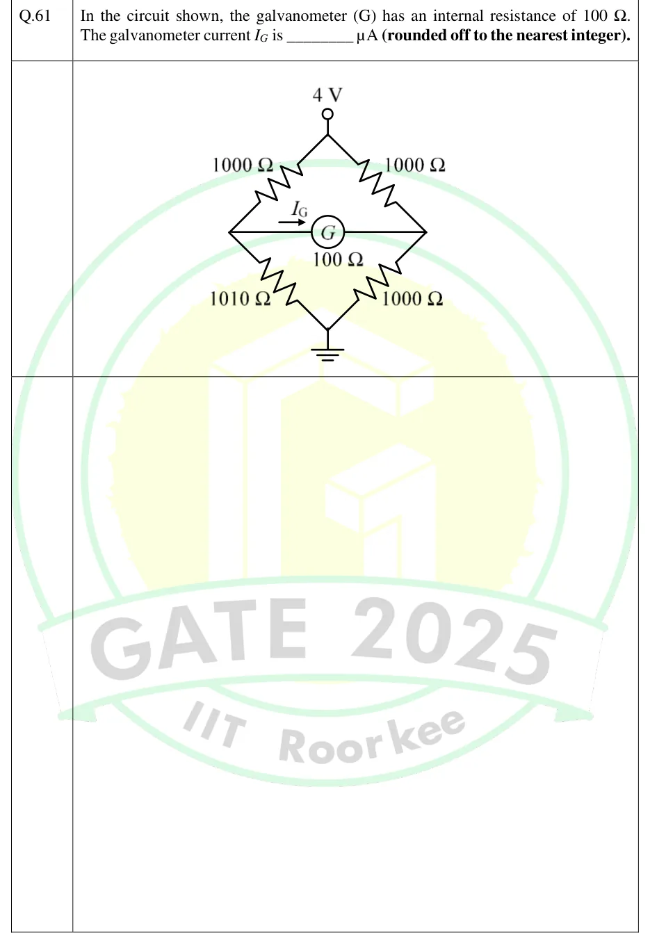
In the circuit shown, the galvanometer (G) has an internal resistance of 100 Ω. The galvanometer current is ________ μA (rounded off to the nearest integer).

GATE 2025 IN question 61: A Wheatstone bridge drawn as a diamond.Tap to open full size
Figure from the GATE 2025 IN paper. It is part of the question.
Figure description

A Wheatstone bridge drawn as a diamond. The top vertex is a terminal held at 4 V (with respect to ground); the bottom vertex is connected to ground. Left arm: a 1000 Ω resistor from the top vertex to the left node, then a 1010 Ω resistor from the left node down to the grounded bottom vertex. Right arm: a 1000 Ω resistor from the top vertex to the right node, then a 1000 Ω resistor from the right node down to the grounded bottom vertex. A galvanometer G of internal resistance 100 Ω is connected horizontally between the left node and the right node. The current I_G is marked by an arrow pointing to the right, i.e. flowing from the left node through G to the right node.

Answer and solution
GATE 2025 IN Q.61: answer and solution

GATE 2024 EC Q.62

GATE 2024 · ECQ.62 · 2 marks · NAT

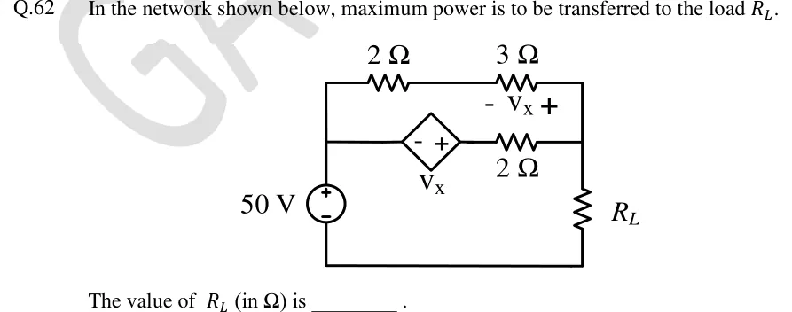
In the network shown below, maximum power is to be transferred to the load .

[Figure]

The value of (in ) is ________ .

GATE 2024 EC question 62: A 50 V independent DC source sits in the left vertical branch, + terminal at the top.Tap to open full size
Figure from the GATE 2024 EC paper. It is part of the question.
Figure description

A 50 V independent DC source sits in the left vertical branch, + terminal at the top. Its top terminal connects to a left vertical wire, called node A here. Its bottom terminal connects to the bottom wire, which is the reference node. The right vertical wire is node B, and the load resistor R_L runs from node B down to the bottom wire. Two parallel branches connect node A to node B. (1) Top branch: a 2 Ω resistor in series with a 3 Ω resistor. The voltage across the 3 Ω resistor is labelled V_x, with - on the left end (the junction between the 2 Ω and the 3 Ω) and + on the right end (node B). (2) Middle branch: a dependent voltage source (diamond) of value V_x, with - on its left (node A side) and + on its right. It is in series with a 2 Ω resistor that goes to node B. The dependent source is controlled by V_x, the voltage across the 3 Ω resistor.

Answer and solution
GATE 2024 EC Q.62: answer and solution

GATE 2023 EE Q.51

GATE 2023 · EEQ.51 · 2 marks · NAT

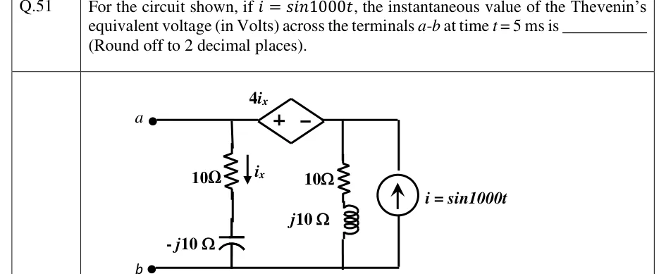
For the circuit shown, if , the instantaneous value of the Thevenin's equivalent voltage (in Volts) across the terminals - at time ms is ______ (Round off to 2 decimal places).

GATE 2023 EE question 51: Three parallel paths between a top rail and a bottom rail.Tap to open full size
Figure from the GATE 2023 EE paper. It is part of the question.
Figure description

Three parallel paths between a top rail and a bottom rail. Terminal a is at the left end of the top rail, and terminal b is at the left end of the bottom rail, which is the common return. Going right from a, the top rail reaches node A. Branch 1 runs from node A down to the bottom rail: a 10 Ω resistor in series with a capacitor of impedance -j10 Ω. Its current i_x flows downward. Continuing right from node A along the top rail is a diamond-shaped dependent voltage source 4i_x, with + on the left (node A side) and - on the right. The source's right end is node B. Branch 2 runs from node B down to the bottom rail: a 10 Ω resistor in series with an inductor of impedance j10 Ω. At the far right, an independent current source i = sin 1000t connects the bottom rail to node B, with its arrow pointing up, so it pushes current into node B. Terminals a-b are open.

Answer and solution
GATE 2023 EE Q.51: answer and solution

GATE 2023 IN Q.31

GATE 2023 · INQ.31 · 1 mark · NAT

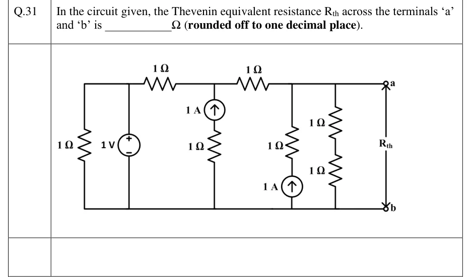
In the circuit given, the Thevenin equivalent resistance across the terminals 'a' and 'b' is ________ (rounded off to one decimal place).

GATE 2023 IN question 31: Planar ladder circuit with a common bottom rail that is terminal b.Tap to open full size
Figure from the GATE 2023 IN paper. It is part of the question.
Figure description

Planar ladder circuit with a common bottom rail that is terminal b. Top node P (far left): a vertical 1 Ω resistor from P down to the bottom rail, and next to it an independent 1 V voltage source from P to the bottom rail, + terminal at the top (at P). A horizontal 1 Ω resistor on the top wire runs from P to node Q. From Q a vertical branch goes down to the bottom rail: a 1 A independent current source (arrow pointing up, toward Q) in series with a 1 Ω resistor below it. A second horizontal 1 Ω resistor on the top wire runs from Q to node R. The top wire continues from R to terminal a at the far right. From R to the bottom rail there are two vertical branches in parallel: (i) a 1 Ω resistor in series with a 1 A independent current source below it (arrow pointing up, toward R); (ii) two 1 Ω resistors in series. Terminals a (top right, on node R) and b (bottom right, on the bottom rail), with R_th marked between them.

Answer and solution
GATE 2023 IN Q.31: answer and solution

GATE 2022 EC Q.54

GATE 2022 · ECQ.54 · 2 marks · NAT

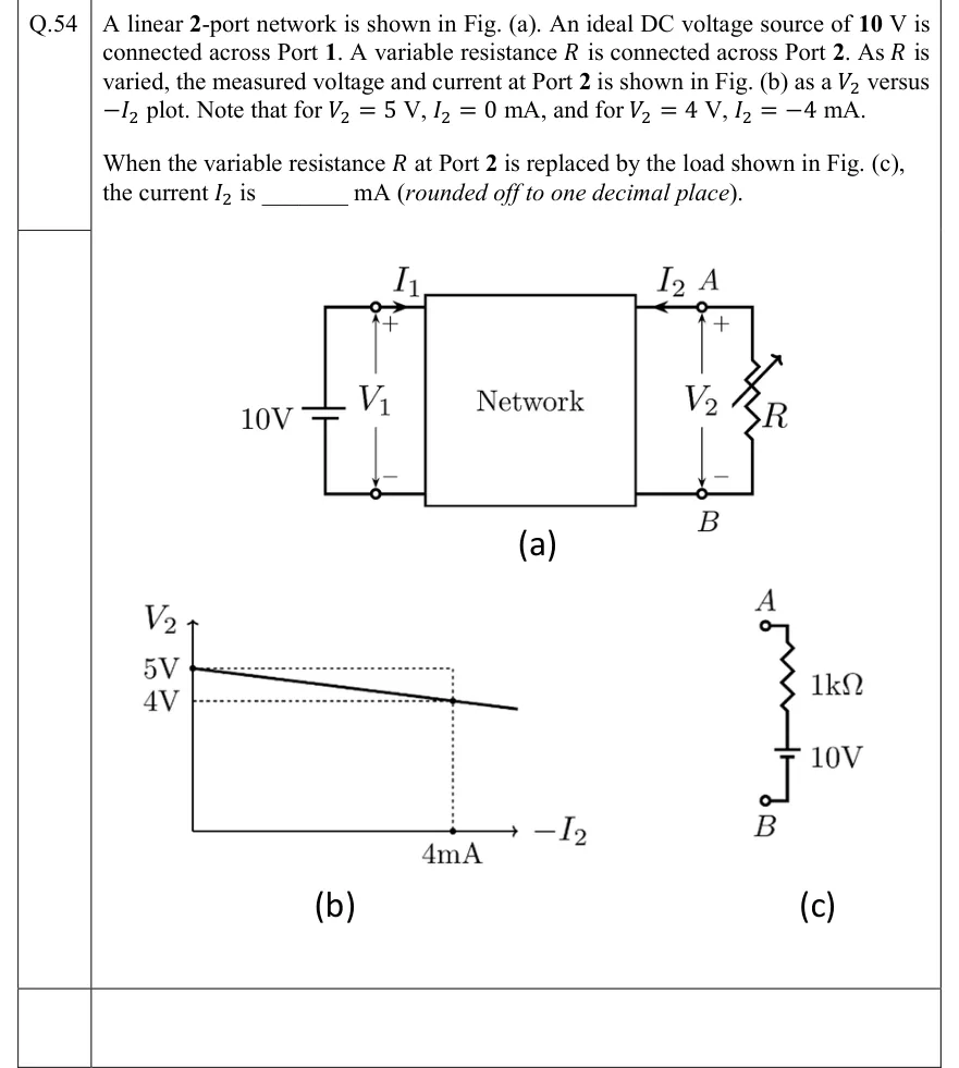
A linear 2-port network is shown in Fig. (a). An ideal DC voltage source of 10 V is connected across Port 1. A variable resistance is connected across Port 2. As is varied, the measured voltage and current at Port 2 is shown in Fig. (b) as a versus plot. Note that for , , and for , .

When the variable resistance at Port 2 is replaced by the load shown in Fig. (c), the current is ________ mA (rounded off to one decimal place).

GATE 2022 EC question 54: Fig.Tap to open full size
Figure from the GATE 2022 EC paper. It is part of the question.
Figure description

Fig. (a): A box labelled 'Network' with two ports. Port 1 (left): an ideal 10 V battery connected across it, long (positive) plate on top; port voltage V_1 with + at the top terminal and − at the bottom; current I_1 enters the top terminal of port 1 flowing into the network. Port 2 (right): top terminal labelled A, bottom terminal labelled B; port voltage V_2 with + at A and − at B; current I_2 drawn with the arrow pointing from A into the network (i.e. I_2 enters the network at A). A variable resistor R (resistor with a diagonal arrow) is connected between A and B. Fig. (b): Plot of V_2 (vertical axis) versus -I_2 (horizontal axis). A straight line with negative slope starts at V_2 = 5 V on the vertical axis (-I_2 = 0) and passes through V_2 = 4 V at -I_2 = 4 mA (dotted guide lines mark 5 V, 4 V and 4 mA), continuing slightly beyond. Fig. (c): The replacement load between terminals A (top) and B (bottom): from A, a 1 k Ω resistor in series with a 10 V battery down to B; the battery's long (positive) plate faces the resistor/A side and the short (negative) plate faces B (same drawing convention as the port-1 source, whose positive plate is at the V_1 '+' terminal).

Answer and solution
GATE 2022 EC Q.54: answer and solution

GATE 2022 IN Q.42

GATE 2022 · INQ.42 · 2 marks · MCQ

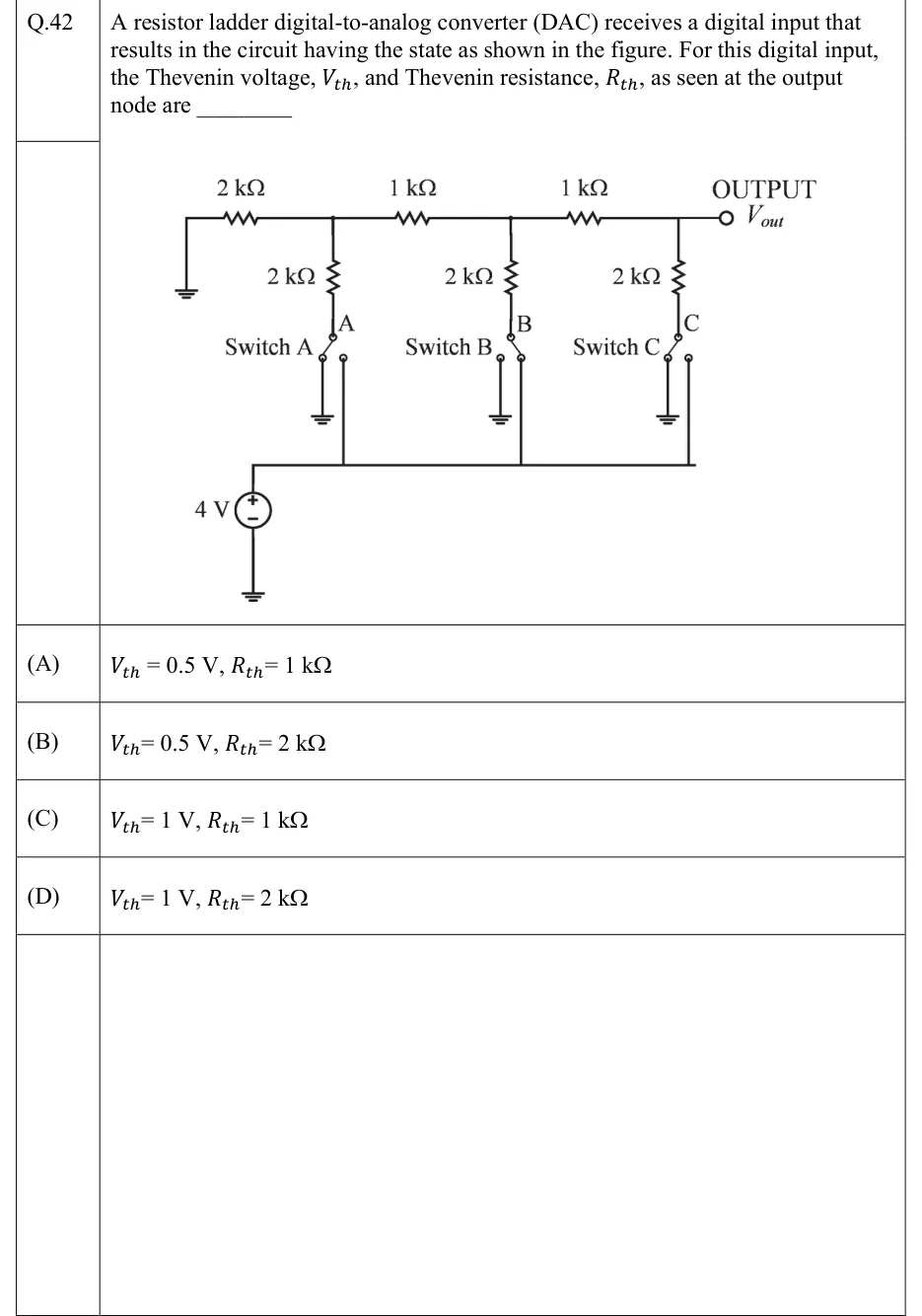
A resistor ladder digital-to-analog converter (DAC) receives a digital input that results in the circuit having the state as shown in the figure. For this digital input, the Thevenin voltage, , and Thevenin resistance, , as seen at the output node are ________

GATE 2022 IN question 42: R-2R ladder.Tap to open full size
Figure from the GATE 2022 IN paper. It is part of the question.
Figure description

R-2R ladder. The top rail runs left to right: its left end goes straight down to ground, then a 2 kΩ series resistor to node A-top, then a 1 kΩ series resistor to node B-top, then a 1 kΩ series resistor to node C-top, which continues to the terminal labelled OUTPUT, V_out. From each of the three rail nodes a 2 kΩ shunt resistor hangs downward to the common pole of a single-pole double-throw switch (labelled A, B, C from left to right, called Switch A, Switch B, Switch C). Each switch has two throws: the left throw goes to ground, the right throw goes to a common horizontal bus that is fed by a 4 V source (positive terminal up to the bus, negative terminal to ground). Switch positions as drawn: Switch A on the left throw (ground), Switch B on the right throw (4 V bus), Switch C on the left throw (ground).

  1. (A)

    ,

  2. (B)

    ,

  3. (C)

    ,

  4. (D)

    ,

Answer and solution
GATE 2022 IN Q.42: answer and solution

GATE 2022 IN Q.54

GATE 2022 · INQ.54 · 2 marks · NAT

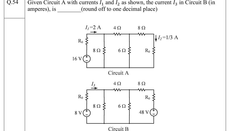
Given Circuit A with currents and as shown, the current in Circuit B (in amperes), is ________ (round off to one decimal place)

GATE 2022 IN question 54: Two separate ladder circuits, A and B, each with its own bottom rail (the reference node).Tap to open full size
Figure from the GATE 2022 IN paper. It is part of the question.
Figure description

Two separate ladder circuits, A and B, each with its own bottom rail (the reference node). Circuit A: The left branch has a 16 V source (+ terminal on top) with R_0 in series above it, running from the bottom rail up to the top wire. Current I_1 = 2 A is marked by an arrow pointing right in the top wire, from R_0 into top node 1. Node 1 has an 8 Ω resistor down to the bottom rail. A 4 Ω series resistor on the top wire joins node 1 to node 2. Node 2 has a 6 Ω resistor down to the bottom rail. An 8 Ω series resistor on the top wire joins node 2 to node 3. Node 3 has a resistor R_0 down to the bottom rail, and the current through it is marked I_2 = 1/3 A flowing downward. Circuit B: The ladder is the same: 8 Ω shunt at node 1, 4 Ω series, 6 Ω shunt at node 2, 8 Ω series. The left branch is an 8 V source (+ terminal on top) with R_0 in series above it. Current I_3 is marked by an arrow pointing right in the top wire, from R_0 into node 1. The rightmost branch, from node 3 to the bottom rail, is R_0 in series with a 48 V source (+ terminal on top, source below R_0).

Answer and solution
GATE 2022 IN Q.54: answer and solution

GATE 2020 EC Q.9

GATE 2020 · ECQ.9 · 1 mark · MCQ

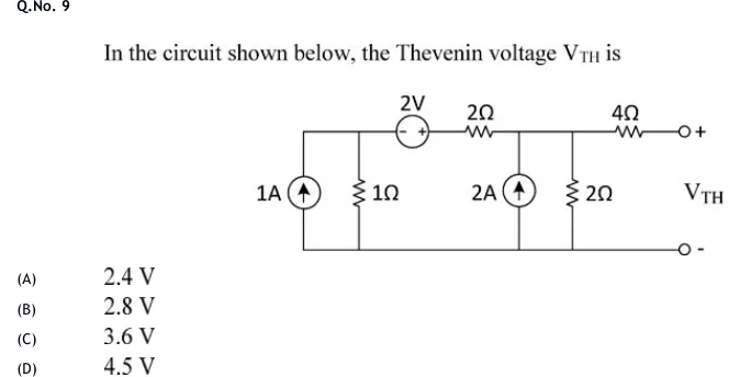
In the circuit shown below, the Thevenin voltage is

GATE 2020 EC question 9: A ladder circuit with a common bottom (reference) rail.Tap to open full size
Figure from the GATE 2020 EC paper. It is part of the question.
Figure description

A ladder circuit with a common bottom (reference) rail. Left node A (top-left): a 1 A independent current source (arrow pointing up, i.e. current delivered into node A) and a 1 Ω resistor, both connected between node A and the bottom rail. From node A the top wire runs right through a 2 V independent voltage source (polarity marked '- +': negative terminal on the left/node-A side, positive terminal on the right) and then a 2 Ω series resistor to node B. At node B: a 2 A independent current source (arrow pointing up, current delivered into node B) and a 2 Ω resistor, both connected between node B and the bottom rail. From node B a 4 Ω series resistor runs right to the open output terminal marked '+'. The bottom rail extends right to the output terminal marked '-'. V_TH is the open-circuit voltage between the '+' and '-' terminals.

  1. (A)

    2.4 V

  2. (B)

    2.8 V

  3. (C)

    3.6 V

  4. (D)

    4.5 V

Answer and solution
GATE 2020 EC Q.9: answer and solution

GATE 2020 EE Q.19

GATE 2020 · EEQ.19 · 1 mark · NAT

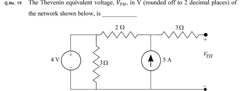
The Thevenin equivalent voltage, , in V (rounded off to 2 decimal places) of the network shown below, is ________

GATE 2020 EE question 19: The circuit has a common bottom (reference) rail and a top rail, reading left to right.Tap to open full size
Figure from the GATE 2020 EE paper. It is part of the question.
Figure description

The circuit has a common bottom (reference) rail and a top rail, reading left to right. Far left: an independent 4 V voltage source, + terminal at the top, connected between the top-left node (call it A) and the bottom rail. Right next to it, also between node A and the bottom rail, is a 3 Ω resistor, so it sits in parallel with the 4 V source. From node A a 2 Ω resistor runs along the top to node B. Between node B and the bottom rail is an independent 5 A current source whose arrow points upward, so it pushes current into node B. From node B a 3 Ω resistor runs along the top to an open terminal marked +. Directly below it, the bottom rail ends in an open terminal marked −. The open-circuit voltage between these two terminals is labelled V_TH.

Answer and solution
GATE 2020 EE Q.19: answer and solution

GATE 2020 IN Q.49

GATE 2020 · INQ.49 · 2 marks · NAT

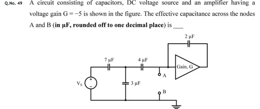
A circuit consisting of capacitors, DC voltage source and an amplifier having a voltage gain G = −5 is shown in the figure. The effective capacitance across the nodes A and B (in µF, rounded off to one decimal place) is ____

GATE 2020 IN question 49: Ladder circuit with an amplifier.Tap to open full size
Figure from the GATE 2020 IN paper. It is part of the question.
Figure description

Ladder circuit with an amplifier. On the left is a DC voltage source V_s, + terminal at the top and − at the bottom. A top wire runs from V_s(+) through a series 7 µF capacitor to an internal node X. A 3 µF capacitor is connected from node X down to the bottom (common) wire. From node X a series 4 µF capacitor leads to node P. Node P is the input of a triangular amplifier labelled 'Gain, G' that points right. Terminal A is a small open circle hanging just below node P. A 2 µF capacitor is connected between node P (by a wire that rises above the amplifier) and the amplifier output at its right-hand tip, so it is a feedback capacitor from output to input. The bottom wire joins V_s(−), the lower plate of the 3 µF capacitor and terminal B (a small open circle), and ends in a ground symbol at the right. The amplifier output goes nowhere except to the 2 µF capacitor. G = −5.

Answer and solution
GATE 2020 IN Q.49: answer and solution

GATE 2018 IN Q.7

GATE 2018 · INQ.7 · 1 mark · MCQ

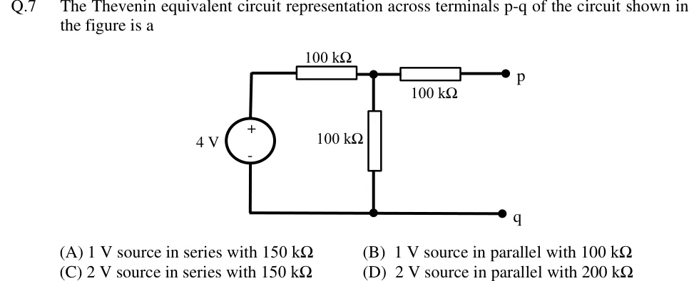
The Thevenin equivalent circuit representation across terminals p-q of the circuit shown in the figure is a

GATE 2018 IN question 7: A 4 V independent voltage source sits on the left, + terminal at the top and - terminal at the bottom.Tap to open full size
Figure from the GATE 2018 IN paper. It is part of the question.
Figure description

A 4 V independent voltage source sits on the left, + terminal at the top and - terminal at the bottom. From its + terminal the top wire runs through a 100 kΩ series resistor to a junction node. From that junction a vertical 100 kΩ resistor goes down to the bottom wire (the shunt branch). Also from the junction, a second 100 kΩ series resistor runs to the right to open terminal p. The bottom wire joins the source's - terminal, the lower end of the shunt 100 kΩ resistor, and open terminal q. Nothing is connected across p-q.

  1. (A)

    1 V source in series with 150 kΩ

  2. (B)

    1 V source in parallel with 100 kΩ

  3. (C)

    2 V source in series with 150 kΩ

  4. (D)

    2 V source in parallel with 200 kΩ

Answer and solution
GATE 2018 IN Q.7: answer and solution

GATE 2018 IN Q.30

GATE 2018 · INQ.30 · 2 marks · NAT

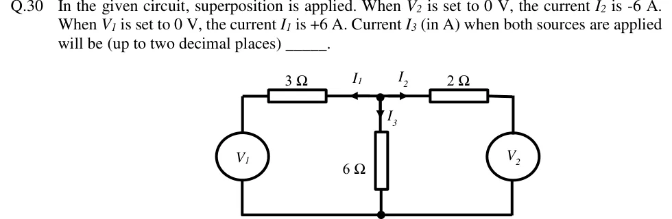
In the given circuit, superposition is applied. When is set to 0 V, the current is A. When is set to 0 V, the current is A. Current (in A) when both sources are applied will be (up to two decimal places) ______.

GATE 2018 IN question 30: Two-mesh circuit with a common bottom (reference) wire.Tap to open full size
Figure from the GATE 2018 IN paper. It is part of the question.
Figure description

Two-mesh circuit with a common bottom (reference) wire. Left branch: independent voltage source V_1 (circle, no polarity marks shown) connected from the bottom wire up to the top-left corner, then a 3 Ω resistor along the top wire to a central top node (call it A). Right branch: from node A a 2 Ω resistor along the top wire to the top-right corner, then down through independent voltage source V_2 (circle, no polarity marks shown) to the bottom wire. Middle branch: a 6 Ω resistor from node A straight down to the bottom wire (a dot marks the junction on the bottom wire). Current reference directions, all drawn at node A: I_1 on the top wire pointing left (from A toward the 3 Ω resistor), I_2 on the top wire pointing right (from A toward the 2 Ω resistor), I_3 pointing downward from A into the 6 Ω resistor. So all three currents are defined as leaving node A.

Answer and solution
GATE 2018 IN Q.30: answer and solution

PRACTICE

5 questions to test yourself

PRACTICE 11 mark · MCQ

A linear circuit contains two independent sources, A and B. With only A active (B set to zero), a resistor R carries A. With only B active (A set to zero), R carries A in the same direction. With both sources active, the power dissipated in R is

  1. (A)

    W

  2. (B)

    W

  3. (C)

    W

  4. (D)

    W

Answer and solution

Answer: (B)

  1. By superposition, the currents add: A.

  2. W.

  3. Option A adds the individual powers () and so drops the cross term W. Option C would apply if the currents were opposite ( A).

PRACTICE 22 marks · NAT

A V independent source (positive terminal up, negative terminal on the reference node) is connected through a resistor to node x. Let be the current in the resistor, flowing from the source towards x. A series branch connects node x to the reference node: a resistor attached to x, followed by a current-controlled voltage source of value volts. The positive terminal of this source is at the resistor end and its negative terminal is at the reference node. A variable resistor is connected between x and the reference node. The maximum power (in W) that can be delivered to is ______.

Answer and solution

Answer: (accepted range )

  1. Open circuit. The branch current flowing down from x is , and KCL at x makes it equal to . So . With this gives A and V.

  2. Short circuit (): A. The branch current flowing down is A, meaning A flows up into x. So A.

  3. . Test-source check (source shorted, at x): and the downward branch current is . So , confirming .

  4. W.

PRACTICE 32 marks · MSQ

Which of the following statements is/are correct?

  1. (A)

    Tellegen's theorem, , holds for a network containing nonlinear and time-varying elements, provided the branch voltages satisfy KVL, the branch currents satisfy KCL, and every branch uses associated reference directions.

  2. (B)

    In a linear network containing dependent sources, the Thevenin resistance seen at a pair of terminals can be negative.

  3. (C)

    While applying superposition, every dependent source is replaced by a short circuit (if it is a voltage source) or an open circuit (if it is a current source), along with the independent sources that are not acting.

  4. (D)

    Whenever a load resistor equals the Thevenin resistance of the linear resistive network feeding it, exactly half of the total power supplied by the independent sources inside the network is delivered to the load.

Answer and solution

Answer: (A), (B)

  1. A is true. Tellegen's theorem depends only on KCL, KVL and the graph, not on what the elements are.

  2. B is true. Example: a resistor across a–b in parallel with a dependent source that injects twice the resistor current into a. A test voltage gives , so .

  3. C is false. Dependent sources are never switched off in superposition.

  4. D is false. The 50% figure holds only for the Thevenin equivalent. Counter-example: a V source, in series and in shunt gives and V. With , W while the source delivers W, so only reaches the load.

PRACTICE 42 marks · MCQ

At the operating frequency, the Thevenin equivalent of a network at its load terminals is V (rms) in series with . The load is a pure resistor whose value is chosen to maximise the average power it absorbs. This maximum average power is

  1. (A)

    W

  2. (B)

    W

  3. (C)

    W

  4. (D)

    W

Answer and solution

Answer: (B)

  1. For a pure-resistor load, .

  2. , so W.

  3. Check: W.

  4. Option A, , would need a conjugate-matched load, which is not allowed here. Option C is what the wrong choice gives: W, which is less than the maximum.

PRACTICE 51 mark · NAT

An inverting amplifier stage has voltage gain with the capacitor below connected. A pF capacitor is connected between its input and output nodes. Using Miller's theorem, the equivalent capacitance (in pF) from the input node to ground due to this capacitor is ______.

Answer and solution

Answer: (accepted range )

  1. Miller input capacitance: with .

  2. pF.

  3. For reference, the output-side capacitance is pF.

OFFICIAL GATE 2027 SYLLABUS WORDING

Copied from the GATE 2027 syllabus; see all 2027 syllabi.

GATE EC

superposition, Thevenin's theorem, Norton’s theorem, reciprocity … maximum power transfer

GATE EE

Network Theorems: Thevenin’s, Norton’s, Superposition and Maximum Power Transfer theorem

GATE IN

superposition, Thevenin’s, Norton’s, Miller’s, maximum power transfer and reciprocity theorems

Preparing in Kolkata? IAE Academy's course for GATE ECE, GATE EE or GATE IN.