
IAE Academy

GATE 2026 EE Q.24: solution and answer

GATE 2026 · EEQ.24 · 1 mark · MCQ

For the circuit shown, which one of the following options correctly identifies the Thevenin's equivalent parameters between nodes Y and Z?
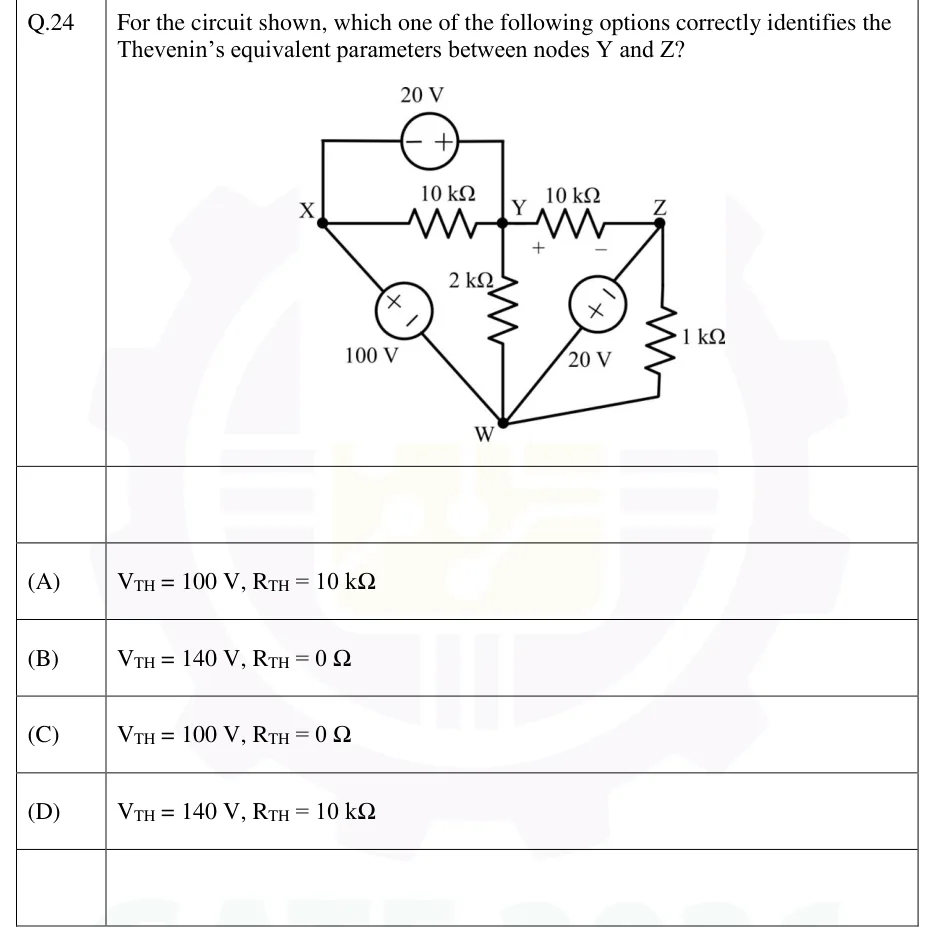
GATE 2026 EE question 24: Four nodes: X (left), Y (top middle), Z (top right), W (bottom middle).Tap to open full size
Figure from the GATE 2026 EE paper. It is part of the question.
Figure description

Four nodes: X (left), Y (top middle), Z (top right), W (bottom middle). Branches: (1) a 20 V independent voltage source on a top wire running from X up, across and down to Y, with its '-' terminal on the X side and '+' terminal on the Y side; (2) a 10 kOhm resistor directly between X and Y, in parallel with that 20 V source; (3) a 10 kOhm resistor between Y and Z, marked '+' at the Y end and '-' at the Z end; (4) a 100 V independent voltage source on the diagonal from X down to W, '+' toward X and '-' toward W; (5) a 2 kOhm resistor vertically between Y and W; (6) a 20 V independent voltage source on the diagonal from Z down to W, '-' toward Z and '+' toward W; (7) a 1 kOhm resistor between Z and W (right side). The Thevenin equivalent is asked between Y and Z.

  1. (A)

    ,

  2. (B)

    ,

  3. (C)

    ,

  4. (D)

    ,

Answer and solution

ANSWER

and , which is option (B).

Official answer: BSource: Official answer key, GATE 2026 EE (IIT Guwahati)

  1. Take W as the reference node: .

  2. The 100 V source between X and W has its terminal toward X, so .

  3. The top 20 V source between X and Y has its terminal on the X side and its terminal on the Y side, so .

  4. The right-hand 20 V source between Z and W has its terminal toward W and its terminal toward Z, so .

  5. Every node voltage is set by an ideal voltage source, so the , and resistors only decide how much current each source supplies. None of them changes a node voltage. The figure marks at Y and at Z, so the open-circuit voltage is The same result comes from KVL along the source-only path Y X W Z: .

  6. To find , deactivate the independent sources by replacing each voltage source with a short. This shorts X to Y (top 20 V source), X to W (100 V source) and W to Z (right-hand 20 V source), so Y, X, W and Z all become one node.

  7. Y and Z are then joined by a zero-resistance path that sits in parallel with every resistor, so . Between Y and Z the network therefore behaves as an ideal 140 V source: option (B).

KEY IDEA

If a chain made only of ideal voltage sources connects the two terminals, the open-circuit voltage is just the KVL sum of those sources along the chain (here ), whatever the resistors are. Killing the sources turns that chain into a short across the terminals, so and the Thevenin equivalent is an ideal voltage source.

WATCH OUT FOR

There are two traps. (1) Reading the visible between Y and Z as (options A and D). Once the sources are shorted, that resistor is in parallel with a zero-resistance path through X and W, so it adds no resistance. (2) Misreading the polarity of the right-hand 20 V source, which has its toward W. If it is taken as opposing the other two sources, the sum becomes (options A and C) instead of the correct .

From the GATE 2026 EE paper. Every question of this paper · Download the full paper · All 16 Theorems questions, with notes

More Theorems questions