
IAE Academy

GATE 2025 IN Q.45: solution and answer

GATE 2025 · INQ.45 · 2 marks · MCQ

The bridge circuit, shown in Figure (a), can be equivalently represented using the circuit shown in Figure (b). The values of , , and in the equivalent circuit are
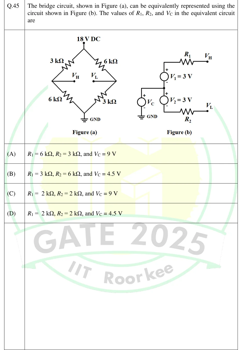
GATE 2025 IN question 45: Figure (a): A diamond-shaped bridge.Tap to open full size
Figure from the GATE 2025 IN paper. It is part of the question.
Figure description

Figure (a): A diamond-shaped bridge. The top vertex connects to an 18 V DC supply and the bottom vertex to GND. Upper-left arm (top to left node): 3 kΩ. Lower-left arm (left node to GND): 6 kΩ. Upper-right arm (top to right node): 6 kΩ. Lower-right arm (right node to GND): 3 kΩ. A wire from the left node goes to an output terminal labelled V_H, and a wire from the right node goes to an output terminal labelled V_L. Nothing is connected between V_H and V_L. Figure (b): A source V_C has its − terminal at GND and its + terminal at a middle node. From the middle node, going up, is source V_1 = 3 V with + at the top and − at the middle node; the + end connects through resistor R_1 to terminal V_H. From the middle node, going down, is source V_2 = 3 V with + at the middle node and − at the bottom; the − end connects through resistor R_2 to terminal V_L.

  1. (A)

    , , and

  2. (B)

    , , and

  3. (C)

    , , and

  4. (D)

    , , and

Answer and solution

ANSWER

, and . This is option (C).

Official answer: CSource: Official answer key, GATE 2025 IN (IIT Roorkee)

  1. Nothing connects to . Both halves of the bridge hang from the same ideal 18 V source, which holds the top node at 18 V whatever current is drawn, so the left arm pair and the right arm pair act as two separate voltage dividers. Each half has its own Thevenin equivalent measured from GND.

  2. Left half, open-circuit voltage by the voltage-divider rule: .

  3. Left half, Thevenin resistance: replace the ideal 18 V source with a short. The and resistors are then in parallel between and GND: .

  4. Right half, voltage-divider rule: . Thevenin resistance: .

  5. In Figure (b), apply KVL from GND to at open circuit. No current flows in , and has its terminal on the side, so . With this gives .

  6. Check along the lower path with KVL. has its terminal at the middle node, so . This matches the divider result, so the equivalent is consistent. In Figure (b) the ideal source also holds the middle node fixed, so the two outputs stay independent, just as they are in Figure (a).

  7. So and , which is option (C).

KEY IDEA

Each half of the bridge is a voltage divider fed by an ideal source, so it reduces to its own Thevenin equivalent measured from GND: behind and behind . Figure (b) splits these into a common-mode part and a differential part. is the common-mode voltage, and is half the bridge's differential output, which is why both are 3 V.

WATCH OUT FOR

Using only the resistor from the output node to GND as the Thevenin resistance. That gives and (option A). When you find the Thevenin resistance, the ideal 18 V source becomes a short, so each output sees both of its arms in parallel: . A second trap is getting the sign of wrong. , not , because the terminal of faces the middle node.

From the GATE 2025 IN paper. Every question of this paper · Download the full paper · All 16 Theorems questions, with notes

More Theorems questions