IAE Academy

IN THE EE AND IN SYLLABUS

Magnetically coupled circuits

Two coils are magnetically coupled when the changing current in one induces a voltage in the other through shared flux; the mutual inductance , the coupling coefficient and the dot convention fix the size and the sign of that voltage. Problems on this topic ask for the mutual terms with the right sign in series and parallel combinations, in mesh equations, in stored energy and in linear and ideal transformers, so a reliable sign procedure matters as much as the formulas.

6 previous-year questions · 6 solved · 6 practice questions

Self inductance, mutual inductance and the coupling coefficient

A coil of inductance produces a voltage from its own changing current. When part of its flux also links a second coil, a changing current in the first coil induces a voltage in the second as well, even though no wire joins them. For linear (air-cored or unsaturated) coils the flux linkage of each coil is a linear combination of both currents: and . and are the self-inductances; (in henry) is the mutual inductance. In a linear medium the coupling is reciprocal: .

itself is always a positive number. The in front of it is decided by the dot markings and by the directions chosen for the currents and voltages (next section), never by the value of . Phasors in these notes are rms values, so average power in a resistor is with the rms magnitude.

TERMINAL EQUATIONS OF TWO COUPLED COILS (TIME DOMAIN)

Each coil's voltage follows the passive sign convention for that coil (+ at the terminal where its own current enters). Use when both currents enter (or both leave) their dotted terminals and when one enters and the other leaves.

PHASOR (SINUSOIDAL STEADY-STATE) FORM

Same sign rule as the time-domain equations. is the mutual reactance in ohms.

S-DOMAIN FORM FOR TRANSIENTS, WITH INITIAL CURRENTS

Unilateral Laplace transform of the time-domain equation, with the same sign rule; follows by swapping the subscripts 1 and 2. The terms in and act as voltage sources in series with the coil.

COUPLING COEFFICIENT

: no coupling; : perfect coupling (all the flux of each coil links the other). Coils wound on a common iron core are typically tightly coupled ( close to 1); air-cored coils are usually more loosely coupled.

MUTUAL INDUCTANCE AND K FROM FLUX

is the flux produced by alone and the part of it that links coil 2 ( turns); and likewise for . Each flux is taken to link every turn of the coil it is counted in. Each fraction is at most 1, which is one way to see why .

COILS ON A COMMON MAGNETIC PATH WITH NO LEAKAGE

Only when all the flux of each coil passes through the same path of reluctance , i.e. .

The dot convention and the sign of the mutual voltage

Whether the mutual voltage adds to or subtracts from the self voltage depends on how the two windings are wound relative to each other, which a circuit diagram cannot show. Dots carry that information: one terminal of each coil is dotted so that currents entering both dotted terminals set up fluxes that aid each other in the shared magnetic path.

Dot rules

  1. A current entering the dotted terminal of one coil induces in the other coil a voltage (phasor ) whose + reference is at the dotted terminal of the other coil.

  2. Equivalently, a current leaving the dotted terminal of one coil induces in the other coil with its + reference at that coil's undotted terminal.

  3. With the passive sign convention on each coil: both currents entering their dots, or both leaving, gives in both terminal equations; one entering and one leaving gives .

  4. If a coil's voltage reference is taken opposite to the passive sign convention, its self term and its mutual term change sign together.

  5. With three or more coupled coils, each pair has its own and its own mark (dot, triangle, square and so on); apply the rule to one pair at a time using only that pair's marks.

  6. Placing dots on a core drawing: use the right-hand rule on each winding; the terminals through which an entering current drives flux the same way round the core form the dotted pair.

  7. Finding dots on real coils: dot any terminal of coil 1, leave coil 2 open with a DC voltmeter across it, and switch on a DC source so that current rises into the dotted terminal of coil 1; the terminal of coil 2 that momentarily goes positive is its dotted terminal.

Current in coil 1

Current in coil 2

Mutual term (passive sign convention on each coil)

enters dot

enters dot

leaves dot

leaves dot

enters dot

leaves dot

leaves dot

enters dot

EXAM TIP

Treat each mutual voltage as a current-controlled voltage source in series with the coil. Mark its + sign on the diagram from the dot rule first; after that, forget the dots and write KVL exactly as for any other source. This keeps all the sign decisions in one place.

Series and parallel connections

In a series connection the same current flows through both coils, so the mutual terms add to the self terms when that current enters both dots (series-aiding) and subtract when it enters one dot and leaves the other (series-opposing). In a parallel connection both coils have the same voltage. For parallel-aiding, ; solving gives and , and gives the result below.

SERIES CONNECTION

for series-aiding (the junction joins an undotted terminal to a dotted one); for series-opposing (dotted to dotted, or undotted to undotted). Both values are non-negative because .

THREE COUPLED COILS IN SERIES

The same current flows through all three coils. Decide each pair separately with that pair's own marks: if the current enters both of the pair's marked terminals (or leaves both), otherwise.

MUTUAL INDUCTANCE FROM TWO SERIES MEASUREMENTS

Measure the series pair, reverse one coil and measure again. The larger reading is always the aiding one.

PARALLEL CONNECTION

in the denominator when like terminals are joined (both dots on the same node: parallel-aiding); when unlike terminals are joined (parallel-opposing). Coil resistances neglected. With the numerator is zero, so , except for two equal coils () in parallel-aiding, where the formula reads and .

Connection

How the terminals are joined

Equivalent inductance

Series-aiding

undotted end of one coil to the dotted end of the other

Series-opposing

dotted to dotted, or undotted to undotted

Parallel-aiding

both dotted ends on the same node

Parallel-opposing

the two dotted ends on opposite nodes

Series with

aiding / opposing

WORKED EXAMPLE · EXAMPLE 1: FINDING M AND K FROM TWO SERIES READINGS

Two magnetically coupled coils in series read 1.9 H on an inductance bridge. With the connections of one coil reversed the reading is 0.7 H. Coil 1 alone reads 0.4 H. Find , and , and the equivalent inductance when the two coils are connected in parallel with their dotted terminals joined.

Solution
  1. The larger reading is series-aiding: H. The smaller is series-opposing: H.

  2. Subtracting: , so H. Adding: , so H and H.

  3. .

  4. Dotted terminals joined is parallel-aiding: H.

  5. For comparison, parallel-opposing would give H.

Answer: H, H, , parallel-aiding H.

EXAM TIP

Series and parallel read the dots in opposite ways. In series, joining unlike terminals (undotted to dotted) is aiding; in parallel, joining like terminals (dot to dot) is aiding. When unsure, trace a current: aiding means it enters both dots or leaves both. Note also that two equal coils with in series-opposition give .

Energy stored and why k cannot exceed 1

The energy stored in coupled coils depends only on the present currents, not on the order in which they were set up. Raise from 0 to with : the stored energy is . Now hold and raise from 0 to : coil 2 absorbs , and coil 1, carrying the constant while the mutual voltage appears across it, absorbs .

ENERGY STORED IN TWO COUPLED COILS

Instantaneous currents. when both currents enter (or both leave) their dotted terminals, otherwise: the same rule as for the voltages.

A passive pair of coils cannot hold negative energy, so for every pair of currents. Take the unfavourable sign () and complete the square in :

COMPLETING THE SQUARE: WHY K CANNOT EXCEED 1

The first term vanishes for , so for all currents requires , i.e. .

AVERAGE STORED ENERGY IN SINUSOIDAL STEADY STATE

, are rms phasors; same sign rule as above.

EXAM TIP

Three consequences: (i) data with describe coils that cannot exist; (ii) the series-opposing inductance satisfies ; (iii) in DC steady state the mutual voltages vanish (no ) and each ideal coil is a short circuit, but the stored energy still contains the term.

Mesh analysis, the T-equivalent and the two-port view

Coupled coils do not change how KVL is written; they only add voltage terms that depend on currents. Mesh analysis is therefore the natural method. Nodal analysis is awkward because a coil's current cannot be written from its own voltage alone without first inverting the inductance matrix.

Mesh analysis with coupled coils

  1. Assign mesh currents. For every coupled coil, write its actual current as the algebraic sum of the mesh currents through it, with a chosen direction (for example downward).

  2. Self voltage of a coil: times that coil current, a drop in the direction of the coil current.

  3. Mutual voltage in coil A: times the current of coil B, positive at A's dotted terminal if B's current enters B's dot and negative there if it leaves. Mark this polarity on the diagram.

  4. Write KVL round each mesh as the sum of drops in the direction of that mesh current. A coil lying in two meshes contributes its self and mutual voltages to both equations; a mesh containing only one of the coupled coils still gets that coil's mutual term.

  5. Check: for a circuit of R, L, C and coupled coils (no dependent sources) the mesh impedance matrix is symmetric, . An asymmetric matrix points to a sign error or a missing mutual term.

The pair of coils can also be treated as a two-port, with port currents and entering the upper terminal of each coil, the lower terminals as the return, and , positive at the upper terminals.

COUPLED COILS AS A TWO-PORT (IMPEDANCE PARAMETERS)

when the two dots are both on the upper terminals (the ones the port currents enter) or both on the lower terminals; when one dot is on an upper terminal and the other on a lower terminal. : the pair is reciprocal.

T-EQUIVALENT OF COUPLED COILS

and are the series arms on the coil-1 and coil-2 sides, the shunt arm to the common terminal. Valid only when the two coils share a common terminal (or their lower terminals are joined in the circuit), because the T adds that connection. "Same side" means both dots away from the common terminal or both on it. A negative inductance in the model is acceptable for analysis, although it is not a physical element.

Π-EQUIVALENT OF COUPLED COILS (DOTS ON THE SAME SIDE)

is the shunt arm across port 1, the shunt arm across port 2 and the series arm joining the two non-common terminals. For dots on opposite sides replace by . It needs a common terminal, as the T does, and so that .

WORKED EXAMPLE · EXAMPLE 2: A COIL SHARED BY TWO MESHES

A source V (rms) has its + terminal at node P and its − terminal at the reference node. Coil 1 ( Ω) is connected from P to node A with its dot at P. Coil 2 ( Ω) is connected from A to the reference node with its dot at A. A 3 Ω resistor is connected from A to the reference node. The coils are coupled with Ω. Find the source current and the average power absorbed by the resistor.

Solution
  1. Check the data: .

  2. Mesh currents: clockwise in the left mesh (source, coil 1, coil 2), clockwise in the right mesh (down through the resistor, up through coil 2). Coil 1 carries into its dot at P; coil 2 carries from A downward, i.e. into its dot at A. Both coil currents enter dots, so the mutual terms are .

  3. Voltage of coil 1 (+ at P): . Voltage of coil 2 (+ at A): .

  4. Mesh 1: .

  5. Mesh 2 (drops in the direction of , which goes up through coil 2): , i.e. . The off-diagonal terms are both , so the matrix is symmetric.

  6. From mesh 2: . Substituting: .

  7. A, and A.

  8. W. Check: W, and the resistor is the only element that absorbs average power.

  9. Check by T-equivalent, with A as the common terminal: coil 1's dot is away from A and coil 2's dot is on A, so the dots are on opposite sides. Arms: Ω from P, Ω from the reference, and Ω to A. The Ω arm in series with the 3 Ω resistor is in parallel with the Ω arm, so Ω, which agrees.

Answer: A (rms), Ω, power in the resistor W.

EXAM TIP

Two errors to avoid. First, using a mesh current instead of the coil's actual current in the mutual term: if coil 2 carries , the voltage it induces in coil 1 is , not . Second, dropping the mutual term from a mesh that contains only one of the two coils: coupling needs no shared wire.

Linear and ideal transformers

A linear transformer is two coupled coils with finite , and , possibly with winding resistances. Let the primary loop have self-impedance (plus any source impedance) and the secondary loop . With entering the primary dot and entering the secondary dot, the mesh equations are and . Eliminating gives the input impedance.

INPUT IMPEDANCE OF A LINEAR TRANSFORMER (REFLECTED IMPEDANCE)

is the whole secondary loop impedance, load included. does not depend on the dot positions ( enters squared), and its reactance has the opposite sign to that of : an inductive secondary reflects as a capacitive reactance.

SECONDARY CURRENT OF A LINEAR TRANSFORMER

With defined as entering the secondary's dotted terminal, as above. Moving one dot, or defining the other way, removes the minus sign; in every case.

INPUT INDUCTANCE WITH THE SECONDARY SHORT-CIRCUITED

Lossless coils, from with . With the secondary open, the input is simply ; comparing the two measurements gives .

An ideal transformer is the limit , no losses, and with held finite. It is described by its turns ratio alone. Convention used here: turns ratio ; and are both positive at the dotted terminals; enters the primary dot and leaves the secondary dot (flows out into the load).

IDEAL TRANSFORMER: VOLTAGE AND CURRENT RATIOS

With the convention above. If one dot is moved to the other end of its winding while the voltage and current references stay on the same physical terminals, both ratios change sign: and . In the two-port convention ( entering the secondary dot) the current relation reads .

IMPEDANCE REFLECTION THROUGH AN IDEAL TRANSFORMER

connected across the secondary; independent of the dot positions. In the other direction, an impedance on the primary side appears on the secondary side as .

POWER CONSERVATION IN AN IDEAL TRANSFORMER

It neither stores nor dissipates energy: complex power in equals complex power out (convention above).

IDEAL TRANSFORMER AS A TWO-PORT (TRANSMISSION PARAMETERS)

Two-port convention: , positive at the dotted terminals, entering the secondary dot, and , . So , , and (reciprocal). The impedance and admittance parameters of an ideal transformer do not exist.

PERFECTLY COUPLED COILS WITH FINITE INDUCTANCE

and positive at the dotted terminals. Coupled coils with behave as an ideal transformer of this turns ratio with the inductance (the magnetizing inductance) connected across its primary. The voltage ratio holds for any load.

Quantity (turns ratio N1 : N2 = n : 1)

Secondary-side value seen from the primary

Primary-side value seen from the secondary

Impedance

Voltage (source or drop)

Current (source or branch)

Polarity or direction of a transferred source

set by the dots

set by the dots

MAXIMUM POWER TRANSFER THROUGH AN IDEAL TRANSFORMER

Resistive source on the primary, resistive load on the secondary, . The load then receives , with the rms source voltage.

Property

Linear transformer (coupled coils)

Ideal transformer

Coupling

any

Described by

, , (and winding resistances)

turns ratio only

Input impedance

Losses and stored energy

possible

none:

What the dots change (fixed reference directions)

sign of and only

sign of and only

EXAM TIP

Read the turns-ratio label before using a formula. A figure marked has , so the load reflects to the primary as , not . Rewrite the ratio as first.

EXAM TIP

Reflected impedance and power do not depend on the dots, but the phase of the secondary voltage and current does. A question asking for as a phasor, or for a meter reading with fixed polarity, is testing the dots. For a linear transformer, : the power absorbed by the reflected resistance is exactly the power delivered to the secondary, a quick check on any answer.

PREVIOUS-YEAR QUESTIONS

6 questions from the EE and IN papers

Try each question first, then open the answer. We placed each question under a topic ourselves; the exam paper does not label topics.

See these papers in full: GATE EE 2025 · GATE EE 2024 · GATE IN 2025 · GATE IN 2024 · GATE IN 2023

GATE 2025 EE Q.52

GATE 2025 · EEQ.52 · 2 marks · MSQ

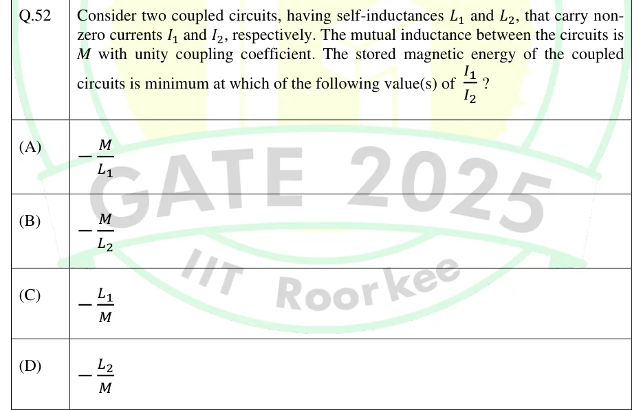
Consider two coupled circuits, having self-inductances and , that carry non-zero currents and , respectively. The mutual inductance between the circuits is with unity coupling coefficient. The stored magnetic energy of the coupled circuits is minimum at which of the following value(s) of ?

  1. (A)

  2. (B)

  3. (C)

  4. (D)

Answer and solution
See the question in the paper
GATE 2025 EE Q.52: answer and solution

GATE 2025 IN Q.24

GATE 2025 · INQ.24 · 1 mark · MCQ

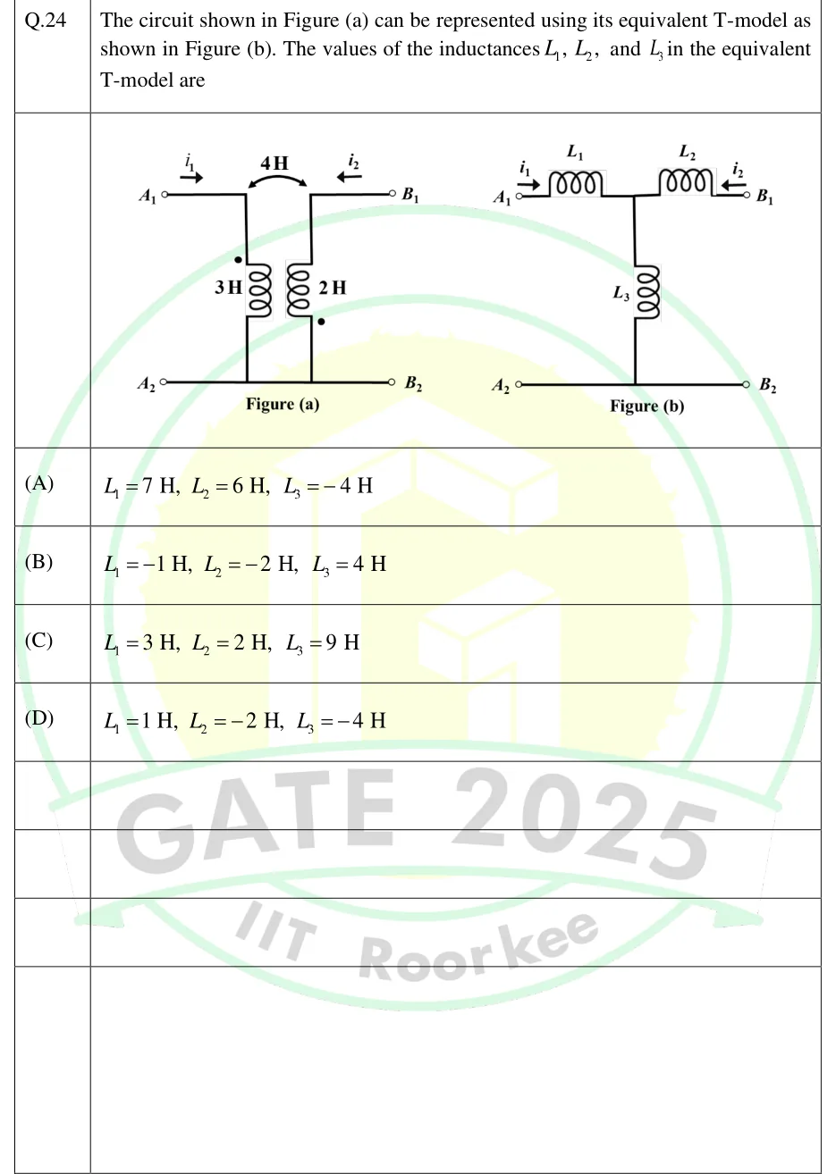
The circuit shown in Figure (a) can be represented using its equivalent T-model as shown in Figure (b). The values of the inductances , , and in the equivalent T-model are

GATE 2025 IN question 24: Figure (a): a two-port made of two magnetically coupled coils.Tap to open full size
Figure from the GATE 2025 IN paper. It is part of the question.
Figure description

Figure (a): a two-port made of two magnetically coupled coils. The left coil, 3 H, is vertical and connects the top-left terminal A_1 (upper wire) to the bottom-left terminal A_2 (lower wire). Its dot is at its TOP end, the end joined to A_1. The right coil, 2 H, is vertical and connects the top-right terminal B_1 (upper wire) to the bottom-right terminal B_2 (lower wire). Its dot is at its BOTTOM end, the end joined to B_2. A curved double-headed arrow between the two coils is labelled 4 H (the mutual inductance). The lower wire runs straight from A_2 to B_2, so A_2 and B_2 are a common node. Current i_1 enters at A_1 (arrow pointing right, into the circuit). Current i_2 enters at B_1 (arrow pointing left, into the circuit). Figure (b): the T-equivalent. L_1 is a series inductor from A_1 to a middle node, L_2 is a series inductor from the middle node to B_1, and L_3 is a shunt inductor from the middle node down to the bottom wire, which joins A_2 to B_2. i_1 enters at A_1 (arrow pointing right) and i_2 enters at B_1 (arrow pointing left).

  1. (A)

    , ,

  2. (B)

    , ,

  3. (C)

    , ,

  4. (D)

    , ,

Answer and solution
GATE 2025 IN Q.24: answer and solution

GATE 2025 IN Q.60

GATE 2025 · INQ.60 · 2 marks · NAT

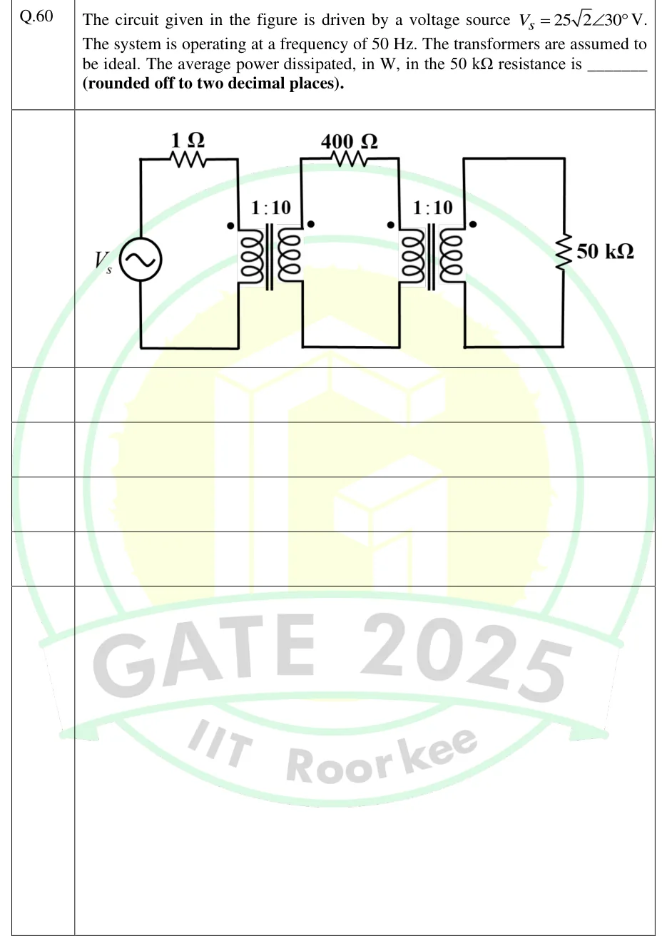
The circuit given in the figure is driven by a voltage source . The system is operating at a frequency of 50 Hz. The transformers are assumed to be ideal. The average power dissipated, in W, in the resistance is ______ (rounded off to two decimal places).

GATE 2025 IN question 60: Three loops coupled by two ideal transformers, left to right.Tap to open full size
Figure from the GATE 2025 IN paper. It is part of the question.
Figure description

Three loops coupled by two ideal transformers, left to right. Loop 1: an AC voltage source V_s (sine symbol) on the left vertical branch, with the top wire running through a 1 Ω resistor to the top of the primary winding of transformer T1; the bottom wire returns from the bottom of the T1 primary to the source. T1 is labelled 1:10 (primary:secondary), iron core shown by two vertical lines, dot at the top of the primary (left side) and dot at the top of the secondary (right side). Loop 2: from the top of the T1 secondary through a 400 Ω resistor to the top of the primary of transformer T2; bottom wire from the bottom of the T1 secondary to the bottom of the T2 primary. T2 is labelled 1:10, dot at the top of its primary and dot at the top of its secondary. Loop 3: the T2 secondary is connected directly across a 50 k Ω resistor on the right vertical branch.

Answer and solution
GATE 2025 IN Q.60: answer and solution

GATE 2024 EE Q.49

GATE 2024 · EEQ.49 · 2 marks · NAT

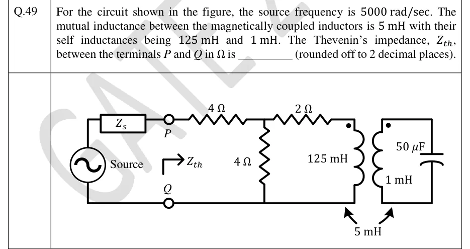
For the circuit shown in the figure, the source frequency is 5000 rad/sec. The mutual inductance between the magnetically coupled inductors is 5 mH with their self inductances being 125 mH and 1 mH. The Thevenin's impedance, , between the terminals and in is ________ (rounded off to 2 decimal places).

GATE 2024 EE question 49: An AC voltage source, labelled 'Source', sits on the far left.Tap to open full size
Figure from the GATE 2024 EE paper. It is part of the question.
Figure description

An AC voltage source, labelled 'Source', sits on the far left. Its top terminal goes through a series impedance Z_s to terminal P. Its bottom terminal goes to terminal Q. P and Q are open terminals, and an arrow labelled Z_th points to the right from them, into the network. From P a series 4 Ω resistor leads to a node A. A shunt 4 Ω resistor connects node A to the bottom rail, which is the Q line. From node A a series 2 Ω resistor leads to the top of a 125 mH inductor, the primary, whose other end goes to the bottom rail. The primary has its dot at the top. The primary is magnetically coupled, with M = 5 mH shown by arrows at the bottom, to a 1 mH secondary inductor, also dotted at the top. The secondary sits in its own isolated loop in series with a 50 capacitor. The secondary loop has no conductive connection to the rest of the circuit.

Answer and solution
GATE 2024 EE Q.49: answer and solution

GATE 2024 IN Q.63

GATE 2024 · INQ.63 · 2 marks · NAT

Two magnetically coupled coils, when connected in series-aiding configuration, have a total inductance of 500 mH. When connected in series-opposing configuration, the coils have a total inductance of 300 mH. If the self-inductance of both the coils are equal, then the coupling coefficient is ________ (rounded off to two decimal places).

Answer and solution
See the question in the paper
GATE 2024 IN Q.63: answer and solution

GATE 2023 IN Q.55

GATE 2023 · INQ.55 · 2 marks · NAT

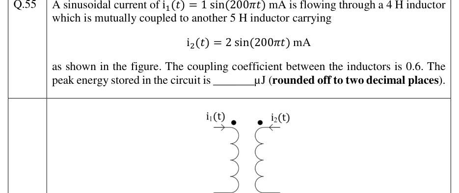
A sinusoidal current of mA is flowing through a 4 H inductor which is mutually coupled to another 5 H inductor carrying

as shown in the figure. The coupling coefficient between the inductors is 0.6. The peak energy stored in the circuit is ________ J (rounded off to two decimal places).

GATE 2023 IN question 55: Two coils side by side, drawn vertically.Tap to open full size
Figure from the GATE 2023 IN paper. It is part of the question.
Figure description

Two coils side by side, drawn vertically. Left coil (the 4 H inductor carrying i1) has its top lead going off to the left; an arrow labelled i1(t) on that top lead points right, so i1 flows into the coil's top terminal. A dot sits at the top end of the left coil. Right coil (the 5 H inductor carrying i2) has its top lead going off to the right; an arrow labelled i2(t) on that top lead points left, so i2 flows into the coil's top terminal. A dot sits at the top end of the right coil. The bottom leads go outward (left coil to the left, right coil to the right). So both currents enter their dotted terminals.

Answer and solution
GATE 2023 IN Q.55: answer and solution

PRACTICE

6 questions to test yourself

PRACTICE 11 mark · NAT

Two magnetically coupled coils have self-inductances H and H. Connected in series-opposing, their equivalent inductance is 6 H. The coefficient of coupling is ______ (rounded off to two decimal places).

Answer and solution

Answer: (accepted range )

  1. Series-opposing: , so and H.

  2. .

PRACTICE 21 mark · MCQ

Two coupled coils have H, H and H. At an instant, current is entering the dotted terminal of coil 1 and increasing at 4 A/s, while current is entering the undotted terminal of coil 2 and increasing at 2 A/s. The voltage across coil 2, taken positive at the terminal where enters, is

  1. (A)

    10 V

  2. (B)

    2 V

  3. (C)

    V

  4. (D)

    V

Answer and solution

Answer: (B)

  1. enters the undotted terminal, i.e. leaves the dot of coil 2, while enters the dot of coil 1. One enters and one leaves, so the mutual term is .

  2. follows the passive sign convention for coil 2: V.

PRACTICE 31 mark · NAT

Two coupled coils have H, H and coefficient of coupling . At an instant, A is entering the dotted terminal of coil 1 and A is leaving the dotted terminal of coil 2. The energy stored in the pair at that instant, in J, is ______ (rounded off to one decimal place).

Answer and solution

Answer: (accepted range )

  1. H.

  2. One current enters its dot and the other leaves its dot, so the mutual term is .

  3. J.

PRACTICE 42 marks · MSQ

Two coupled coils have H, H and coefficient of coupling . Which of the following statements is/are correct?

  1. (A)

    Connected in series-aiding, the equivalent inductance is 19 H.

  2. (B)

    Connected in series-opposing, the equivalent inductance is 1 H.

  3. (C)

    Connected in parallel with the two dotted terminals joined together, the equivalent inductance is H.

  4. (D)

    The largest mutual inductance these two coils could have, with any degree of coupling, is 6.5 H.

Answer and solution

Answer: (A), (C)

  1. H.

  2. Series-aiding: H, so A is correct.

  3. Series-opposing: H, not 1 H. The value H would need . B is wrong.

  4. Dotted terminals joined is parallel-aiding: H. C is correct.

  5. limits to H. 6.5 H is the arithmetic mean of and , which exceeds their geometric mean. D is wrong.

PRACTICE 52 marks · NAT

In a linear transformer circuit, a source V (rms) is connected across the primary winding through a series resistance of 5 Ω. The primary winding has reactance Ω, the secondary winding has reactance Ω, and the mutual reactance is Ω. A 10 Ω resistor is connected across the secondary winding. The windings themselves have no resistance. The average power absorbed by the 10 Ω resistor, in W, is ______ (rounded off to two decimal places).

Answer and solution

Answer: (accepted range )

  1. Ω and Ω.

  2. Reflected impedance: Ω (the dot positions do not matter).

  3. Ω, so and A².

  4. The power absorbed by Ω is the power delivered to the secondary, whose only resistance is the load: W.

  5. Check: A, and W.

PRACTICE 62 marks · MCQ

A source V (rms) in series with a 10 Ω resistor drives the primary of an ideal transformer with turns ratio . The source's + terminal connects, through the resistor, to the upper primary terminal, which carries the primary dot; the source's − terminal connects to the lower primary terminal. On the secondary the dot is on the lower terminal, and a 40 Ω resistor is connected across the secondary. With defined as the voltage of the upper secondary terminal with respect to the lower one, is

  1. (A)

    V

  2. (B)

    V

  3. (C)

    V

  4. (D)

    V

Answer and solution

Answer: (B)

  1. , so the 40 Ω load reflects to the primary as Ω; the dots do not affect this.

  2. A, so the primary voltage with the dotted (upper) terminal positive is V.

  3. The dotted secondary terminal has the same polarity as the dotted primary terminal, with magnitude V: the lower terminal is at V with respect to the upper one.

  4. Hence V. Check: load power W W.

OFFICIAL GATE 2027 SYLLABUS WORDING

Copied from the GATE 2027 syllabus; see all 2027 syllabi.

GATE EE

R, L, C, M elements

GATE IN

coupled inductor

Preparing in Kolkata? IAE Academy's course for GATE EE or GATE IN.