
IAE Academy

GATE 2025 IN Q.60: solution and answer

GATE 2025 · INQ.60 · 2 marks · NAT

The circuit given in the figure is driven by a voltage source . The system is operating at a frequency of 50 Hz. The transformers are assumed to be ideal. The average power dissipated, in W, in the resistance is ______ (rounded off to two decimal places).
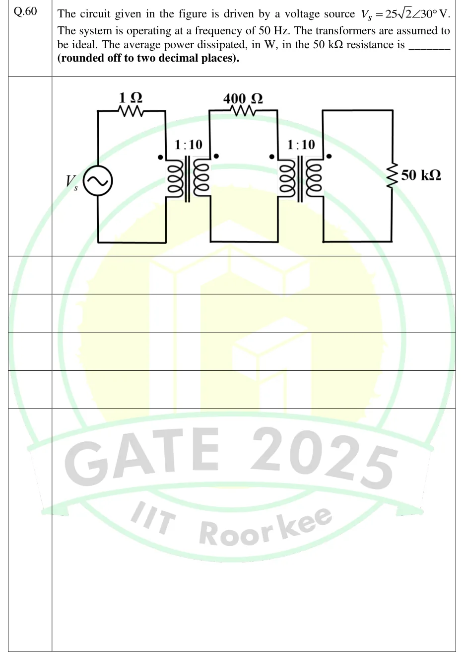
GATE 2025 IN question 60: Three loops coupled by two ideal transformers, left to right.Tap to open full size
Figure from the GATE 2025 IN paper. It is part of the question.
Figure description

Three loops coupled by two ideal transformers, left to right. Loop 1: an AC voltage source V_s (sine symbol) on the left vertical branch, with the top wire running through a 1 Ω resistor to the top of the primary winding of transformer T1; the bottom wire returns from the bottom of the T1 primary to the source. T1 is labelled 1:10 (primary:secondary), iron core shown by two vertical lines, dot at the top of the primary (left side) and dot at the top of the secondary (right side). Loop 2: from the top of the T1 secondary through a 400 Ω resistor to the top of the primary of transformer T2; bottom wire from the bottom of the T1 secondary to the bottom of the T2 primary. T2 is labelled 1:10, dot at the top of its primary and dot at the top of its secondary. Loop 3: the T2 secondary is connected directly across a 50 k Ω resistor on the right vertical branch.

Answer and solution

ANSWER

The average power dissipated in the 50 kΩ resistance is 31.25 W.

Official answer: 31.00 to 31.50Source: Official answer key, GATE 2025 IN (IIT Roorkee)

  1. Reflect the load through T2. An ideal transformer makes an impedance on its secondary look like from its primary. With : The dot positions change only the sign of the transferred voltage and current, not their magnitudes, so they do not affect power.

  2. Middle loop. The T1 secondary now sees in series.

  3. Reflect through T1. , so the source sees . The network is purely resistive, so neither the 50 Hz frequency nor the angle affects the power.

  4. Source magnitude. The phasor is written as . The marks as the peak value (amplitude), so . The official key uses this reading. Taking as the rms value would give , which is outside the key.

  5. Primary current. .

  6. Power delivered past the resistor. Ideal transformers are lossless, so the power into the reflected equals the power into the middle loop:

  7. Split between the and the reflected . Both carry the same current, so the power divides in proportion to resistance: The reflected stands for the load, and T2 is lossless, so this is the power dissipated in the resistor.

  8. Check with currents. Each step-up divides the current by 10. The middle-loop current is , and the load current is . Then

KEY IDEA

Reflect each resistance back toward the source by dividing by n^2 at every ideal 1:n step-up transformer. That turns the whole network into a single 10 Ω load on a 25 V rms source. Ideal transformers are lossless, so the power that reaches the reflected 500 Ω is exactly the power in the 50 kΩ resistor.

WATCH OUT FOR

Three mistakes are common. (1) Reading 25√2 V as the rms value, which doubles the answer to 62.50 W. The √2 means it is the peak value, so V_rms = 25 V. (2) Reflecting the wrong way, multiplying by n^2 instead of dividing, when moving an impedance from the high-turns side to the low-turns side. (3) Forgetting the 400 Ω resistor in the middle loop, which takes 400/900 of the power that gets past the 1 Ω resistor.

From the GATE 2025 IN paper. Every question of this paper · Download the full paper · All 6 Coupled circuits questions, with notes

More Coupled circuits questions