
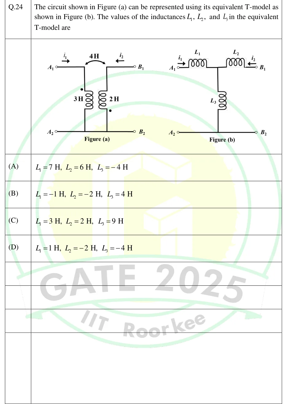
The circuit shown in Figure (a) can be represented using its equivalent T-model as shown in Figure (b). The values of the inductances , , and in the equivalent T-model are
 Tap to open full size
Figure description
Figure (a): a two-port made of two magnetically coupled coils. The left coil, 3 H, is vertical and connects the top-left terminal A_1 (upper wire) to the bottom-left terminal A_2 (lower wire). Its dot is at its TOP end, the end joined to A_1. The right coil, 2 H, is vertical and connects the top-right terminal B_1 (upper wire) to the bottom-right terminal B_2 (lower wire). Its dot is at its BOTTOM end, the end joined to B_2. A curved double-headed arrow between the two coils is labelled 4 H (the mutual inductance). The lower wire runs straight from A_2 to B_2, so A_2 and B_2 are a common node. Current i_1 enters at A_1 (arrow pointing right, into the circuit). Current i_2 enters at B_1 (arrow pointing left, into the circuit). Figure (b): the T-equivalent. L_1 is a series inductor from A_1 to a middle node, L_2 is a series inductor from the middle node to B_1, and L_3 is a shunt inductor from the middle node down to the bottom wire, which joins A_2 to B_2. i_1 enters at A_1 (arrow pointing right) and i_2 enters at B_1 (arrow pointing left).
- (A)
, ,
- (B)
, ,
- (C)
, ,
- (D)
, ,