IAE Academy

IN THE EE SYLLABUS

Balanced three-phase circuits

A balanced three-phase circuit is three equal sinusoidal sources apart feeding identical impedances in every phase, so it can be solved one phase at a time: the other two phases follow by rotating the result through , and the total power is three times the per-phase power. The topic covers the star and delta line/phase relations with their and factors, per-phase analysis with star-delta conversion, three-phase active, reactive and apparent power, the two-wattmeter method including its negative reading, and three-phase power-factor correction.

11 previous-year questions · 11 solved · 5 practice questions

Conventions, phase sequence and phasors

A balanced three-phase source is three sinusoidal voltages of the same frequency and the same rms magnitude, displaced by from each other. A balanced three-phase circuit has a balanced source and identical impedances in all three phases (the load, and the line impedances if any). Everything that makes three-phase problems short, namely per-phase analysis, the relations and zero neutral current, depends on this balance.

Conventions used throughout these notes. Phasors are rms (so the power in one phase is with no factor of 1/2). The phase sequence is positive (abc) with as the reference unless stated otherwise. The per-phase load impedance is : is inductive, i.e. a lagging power factor, and is the angle by which each phase current lags its own phase voltage. Power is absorbed by the load (passive sign convention). A supply described as "400 V, three-phase" means 400 V rms line-to-line unless the question says otherwise.

BALANCED POSITIVE-SEQUENCE (ABC) SET

Phase b lags phase a by and phase c lags phase b by . For negative sequence (acb) the angles of and are interchanged: , .

OPERATOR A AND THE ZERO SUM OF A BALANCED SET

For abc: and . Hence any balanced set sums to zero, , and the same holds for a balanced set of currents.

The phase sequence is the order in which the three phases reach their positive peaks. Phasors rotate counter-clockwise, so in the abc phasor diagram is drawn clockwise from , and a further clockwise (which is counter-clockwise of ). Interchanging any two supply lines reverses the sequence, and with it the direction of rotation of a three-phase induction motor. The sequence decides the sign of the shifts below and which wattmeter reads more in the two-wattmeter method; it does not change any voltage or current magnitude in a balanced circuit.

EXAM TIP

In a balanced star load the three line currents also form a balanced set and sum to zero, so the neutral wire carries no current, the load neutral sits at the source-neutral potential, and removing the neutral changes nothing. That is exactly why a balanced system can be analysed one phase at a time.

Star and delta: line and phase quantities

In a star (wye) connection each phase sits between a line and the neutral, so the phase current is the line current, while each line voltage is the difference of two phase voltages: . With the abc set above, .

In a delta connection each phase sits between two lines, so the phase voltage is the line voltage, while each line current is the difference of two phase currents (KCL at a corner of the delta): , with taken from line a towards line b, and so on round the delta. For a balanced abc set this gives .

STAR: LINE AND PHASE RELATIONS (ABC)

Each line voltage leads the phase voltage of its first subscript by ( leads , leads ). For negative sequence the magnitudes are unchanged but .

DELTA: LINE AND PHASE RELATIONS (ABC)

Phase currents , , are taken in the direction of their subscripts; each line current lags, by , the phase current leaving that line's corner ( lags , lags ). For negative sequence, .

Quantity

Star (Y)

Delta ()

Phase voltage

Phase current

shift (abc)

leads by

lags by

Neutral

Available: three- or four-wire

None: three-wire only

Total active power

Star equivalent for per-phase work

Itself

EXAM TIP

The factors never change; only the shifts flip sign with the phase sequence. If a question gives the sequence as acb (negative), redo the angles, not the magnitudes.

Per-phase equivalent and star-delta conversion

Because a balanced circuit is symmetric, the three phases carry equal current and voltage magnitudes displaced by . So you solve one phase of an equivalent star-star circuit, with the source and load neutrals joined by an ideal wire (it carries no current anyway), and write the other two phases by rotating the result through and (abc). Any delta, source or load, is first replaced by its star equivalent.

BALANCED STAR-DELTA CONVERSION

Identical impedances only. The division is by a real number, so the impedance angle , and hence the power factor, is unchanged.

DELTA SOURCE TO EQUIVALENT STAR (ABC)

Replaces a balanced delta-connected source by a star source for per-phase analysis. For negative sequence use .

Per-phase procedure

  1. Convert every balanced delta, source or load, to star: and .

  2. Draw phase a only: in series with the line impedance and the load . Leave out any neutral-wire impedance; it carries no current in a balanced system.

  3. Solve . Then and .

  4. Load voltages: (star-equivalent phase voltage at the load) and (line voltage at the load).

  5. If the actual load is delta, its phase current is , which also equals .

  6. Multiply per-phase powers by 3 to get totals.

WORKED EXAMPLE · DELTA LOAD FED THROUGH LINE IMPEDANCE

A balanced star-connected source of positive sequence, with V (rms), feeds a balanced delta-connected load of per phase through three lines, each of impedance . Find the line current, the phase current of the delta load, the line voltage at the load, the active power absorbed by the load and the power factor at the source.

Solution
  1. Star equivalent of the load: .

  2. Per-phase series impedance: .

  3. Line current: A, so A.

  4. Delta phase current: A.

  5. Load voltage: V, so the load line voltage is V. Check: V.

  6. Load power: W (equivalently W). The lines dissipate W.

  7. At the source the per-phase impedance angle is , so pf lagging. Check: source W W.

Answer: A; delta phase current A; load line voltage V; load power kW; source power factor lagging (the load's own power factor is lagging).

EXAM TIP

Line impedance changes both the magnitude and the angle of the load voltage, so the load line voltage differs from the source line voltage: for an inductive load fed through an inductive line it is smaller, but with a capacitive load it can be larger. The load power factor and the source power factor therefore differ in general. Take each from its own impedance angle: the angle of for the load, the angle of at the source (they coincide only when and have the same angle). An impedance in the neutral wire of a balanced star-star system has no effect at all.

Three-phase power, and why it is constant

Total power is the sum of the three phase powers. In a balanced load the three are equal, so . Substituting the star or the delta relations gives the same line-quantity form, , for both connections. The angle is always the angle between a phase voltage and its own phase current, i.e. the angle of the per-phase impedance, never the angle between a line voltage and a line current.

THREE-PHASE ACTIVE POWER

Balanced load, star or delta; rms values; = angle of the per-phase impedance. Pair the delta resistance with the delta phase current, or the star-equivalent resistance with the line current.

THREE-PHASE REACTIVE POWER

(absorbed) for an inductive, lagging load; for a capacitive, leading load.

COMPLEX AND APPARENT POWER, POWER FACTOR

and are the phasors of the same phase and is the complex conjugate. is in VA (or kVA); a three-phase kVA figure means this total for all three phases, not the per-phase value.

INSTANTANEOUS POWER OF A BALANCED LOAD

Balanced sinusoidal voltages and a balanced load; , rms. The total does not vary with time and equals the average power .

Why it is constant: let and be the rms phase voltage and current, with and . Then . Phases b and c give the same constant term plus and . The three double-frequency terms form a balanced set at and add to zero, leaving . Each phase on its own still pulsates at ; only the total is steady. That is why a balanced three-phase motor can deliver a steady, non-pulsating torque, whereas the power into a single-phase load always pulsates at .

EXAM TIP

Same three impedances, star versus delta on the same supply: in delta each impedance sees times the voltage, so it draws times the phase current, and the line current is times larger. Hence and .

EXAM TIP

One line or one phase open (three identical impedances on a balanced three-wire supply). Star, one line open: the other two impedances are in series across one line voltage, so the total power falls to 1/2 of its balanced value. Delta, one line open: one impedance stays across the full line voltage and the other two are in series across that same line voltage, again 1/2. Delta, one phase (one impedance) open: the other two still see the full line voltage, so 2/3. These ratios hold for any identical , not only resistors.

EXAM TIP

Trap: in a balanced load (abc, lagging) the angle between and is , and the angle between and is . The cosine of either is not the power factor. They are, however, exactly the two wattmeter angles in the next section.

Power measurement: the two-wattmeter method

A wattmeter reads the average of (voltage across its pressure coil) × (current through its current coil): , where is the angle between those two phasors. In a three-wire system the total power can be measured with two wattmeters: current coils in two lines (say a and c), and both pressure coils connected from those lines to the third line (b).

Why it works for any three-wire load: the instantaneous power delivered through the lines is . With no neutral wire, KCL gives , so , which is exactly what the two meters average. The neutral drops out, so nothing here assumes balance, sinusoidal waveforms or an accessible neutral. In general the power of an -wire system can be measured with wattmeters by returning all the pressure coils to the one remaining line, so an unbalanced four-wire system needs three.

TWO-WATTMETER SUM (ANY THREE-WIRE LOAD)

Readings are taken with their signs. Valid for balanced and unbalanced three-wire loads.

WATTMETER READINGS FOR A BALANCED LOAD

Balanced sinusoidal system. The current coils, in lines a and c, carry the line currents towards the load; the pressure coils measure and (each coil's terminal on its own current-coil line, the other end on line b). For abc sequence the meter in line c reads and the meter in line a reads . The formulas hold for either sign of ( lagging, leading), so a leading load, or a reversed sequence, swaps which meter reads more.

READINGS IN TERMS OF P AND Q (BALANCED LOAD)

The same pair written with and ; handy for predicting the readings when and (or and the power factor) are given. exactly when , i.e. .

POWER-FACTOR ANGLE AND REACTIVE POWER FROM THE READINGS

Balanced load only. Follows from and . The two readings alone fix ; whether the load lags or leads needs either the nature of the load or knowledge of which physical meter reads , which depends on the connection and the phase sequence.

POWER FACTOR DIRECTLY FROM THE READINGS

Balanced load; the same content as the form. Insert a negative reading with its sign.

Load pf (lagging)

What you see

1

Equal readings

0.866

0.5

0

One meter reads zero

Between 0.5 and 0

to

Positive

Negative

0

Equal and opposite;

EXAM TIP

The negative reading. Below 0.5 power factor, is negative and that meter tries to deflect backwards. Its current-coil (or pressure-coil) connections are reversed to get an on-scale reading, and that reading must then be entered as negative: . Adding it as positive is the standard trap.

THREE-WATTMETER AND ONE-WATTMETER METHODS

Three-wattmeter method: one meter per line, each pressure coil from its line to the neutral, so each meter reads one phase power; valid for balanced and unbalanced loads. One-wattmeter method: for a balanced load, a single meter with its current coil in one line and its pressure coil from that line to the neutral (or to an artificial neutral formed by three equal impedances, one of them the pressure coil) reads one-third of the total.

REACTIVE POWER WITH ONE WATTMETER (BALANCED LOAD)

Balanced load, abc sequence. Current coil in line a; pressure coil across lines b and c with its terminal on line b, so it measures . Since lags by , the meter reads rather than a power; the reading is negative for a leading load.

WORKED EXAMPLE · TWO-WATTMETER READINGS, THEN CORRECTION TO UNITY POWER FACTOR

A balanced three-phase, three-wire inductive load on a 400 V (line, rms), 50 Hz supply is metered by the two-wattmeter method; the readings are 8 kW and 2 kW. Find (a) the total active power, the power factor and the reactive power, (b) the line current, and (c) the capacitance per phase of a delta-connected capacitor bank, connected at the load terminals downstream of the meters, that raises the power factor to unity, together with the wattmeter readings after correction.

Solution
  1. kW.

  2. , so and pf , lagging because the load is stated to be inductive. Check with the direct form: .

  3. kvar; kVA.

  4. A.

  5. For unity pf the bank must supply kvar, i.e. kvar per capacitor. Each delta capacitor sees V: . (A star bank would need per phase.)

  6. After correction is unchanged (ideal capacitors absorb no active power) and , so the meters read each, i.e. kW each; the line current falls to A.

Answer: kW, pf lagging, kvar; A; per phase; after correction both wattmeters read 5 kW.

Power-factor correction in three-phase

Shunt capacitors at the load supply part of the lagging reactive power locally. The active power is unchanged (ideal capacitors absorb none), while the kVA and the line current fall. The three capacitors of a balanced bank may be connected in star or in delta; the kvar needed is the same, the capacitance is not.

CAPACITOR KVAR REQUIRED

Total for all three phases; is the original angle and the target angle, both lagging. For a unity target, equals the original .

CAPACITANCE PER PHASE OF THE BANK

= line voltage (rms), . Each star capacitor sees and supplies ; each delta capacitor sees the full and supplies .

EXAM TIP

A delta bank needs one-third the capacitance of a star bank for the same kvar, but each of its capacitors must be rated for the full line voltage instead of . Watch whether a question asks for total kvar, kvar per phase, or capacitance per phase.

Unbalanced loads (in brief)

If the three phase impedances differ, the symmetry of the currents is lost and per-phase analysis no longer applies; each phase has to be solved on its own. The source is normally still balanced.

How each case is solved

  1. Star, four-wire (ideal neutral, no line impedance): each phase is independent, , , , and the neutral carries , which is in general not zero. (A line impedance simply adds in series to its own phase impedance.)

  2. Star, three-wire (no neutral): the load neutral N' shifts away from the source neutral N by (formula below). Then , and similarly for b and c; the line currents still add to zero.

  3. Delta with no line impedance: each phase sees a known line voltage, so and so on directly; the line currents follow from KCL, e.g. .

  4. Power: add the three phase powers. The two-wattmeter sum still gives the total active power of a three-wire load, but the and results do not apply.

NEUTRAL-SHIFT VOLTAGE (UNBALANCED STAR, NO NEUTRAL)

Nodal equation at N', with the source phase voltages measured from N; any line impedance is included in . It is zero when , which recovers the balanced case. If N' and N are joined through a neutral impedance , add to the denominator.

EXAM TIP

If the neutral of an unbalanced star load is lost, the load neutral in general shifts (). The load phase voltages , , are then unequal, and at least one of them exceeds the normal value : because the source phase voltages sum to zero, the squares of the three load phase voltage magnitudes add up to , which is more than .

PREVIOUS-YEAR QUESTIONS

11 questions from the EE and IN papers

Try each question first, then open the answer. We placed each question under a topic ourselves; the exam paper does not label topics.

See these papers in full: GATE EE 2024 · GATE EE 2023 · GATE EE 2022 · GATE EE 2018 · GATE IN 2025 · GATE IN 2022 · GATE IN 2020

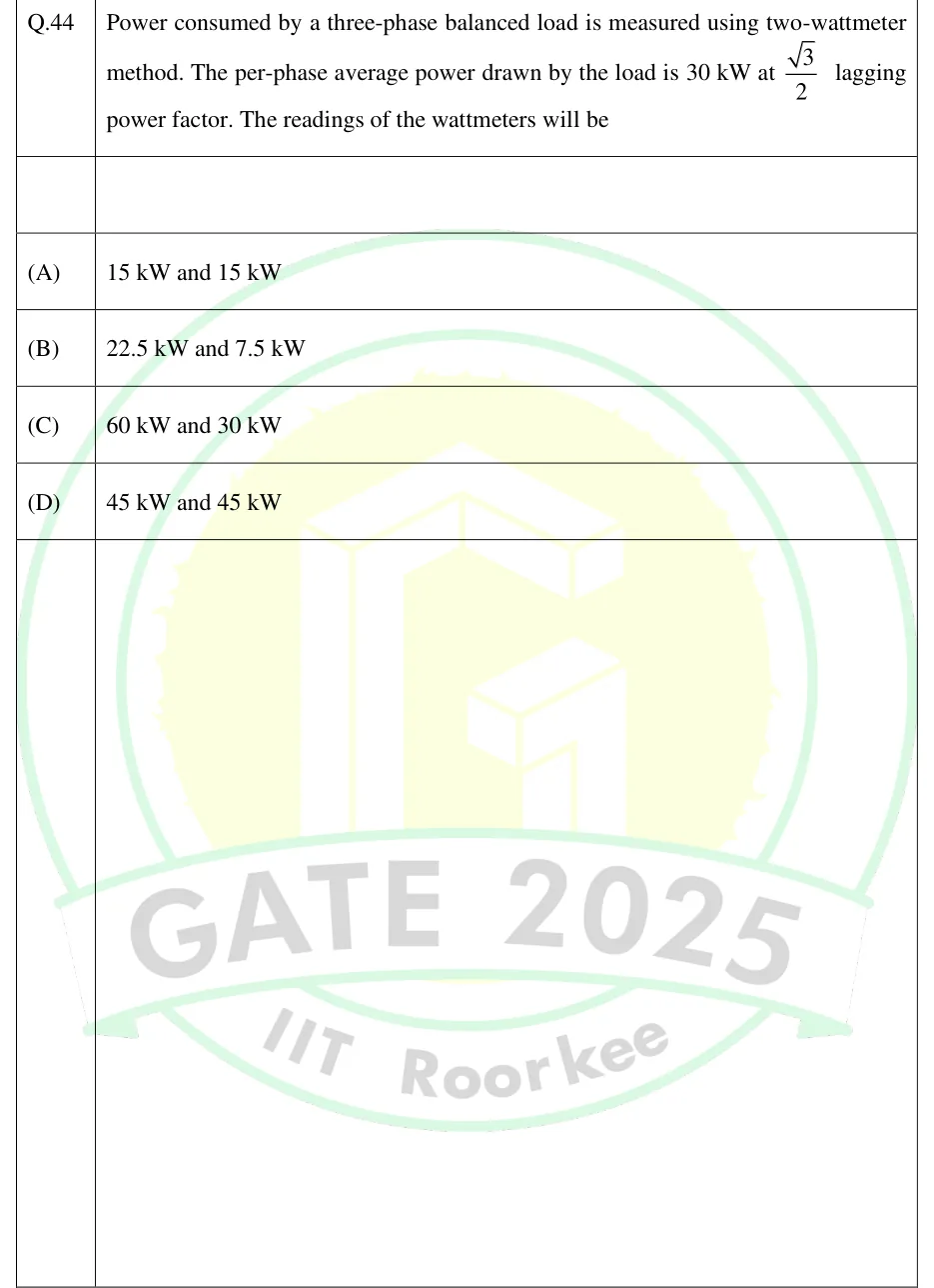
GATE 2025 IN Q.44

GATE 2025 · INQ.44 · 2 marks · MCQ

Power consumed by a three-phase balanced load is measured using two-wattmeter method. The per-phase average power drawn by the load is 30 kW at lagging power factor. The readings of the wattmeters will be

  1. (A)

    15 kW and 15 kW

  2. (B)

    22.5 kW and 7.5 kW

  3. (C)

    60 kW and 30 kW

  4. (D)

    45 kW and 45 kW

Answer and solution
See the question in the paper
GATE 2025 IN Q.44: answer and solution

GATE 2024 EE Q.50

GATE 2024 · EEQ.50 · 2 marks · NAT

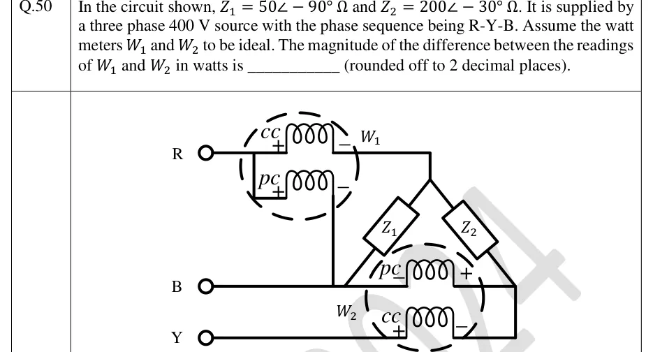
In the circuit shown, and . It is supplied by a three phase 400 V source with the phase sequence being R-Y-B. Assume the watt meters and to be ideal. The magnitude of the difference between the readings of and in watts is ________ (rounded off to 2 decimal places).

GATE 2024 EE question 50: Three supply terminals on the left, top to bottom: R, B, Y (B is drawn in the middle, Y at the bottom).Tap to open full size
Figure from the GATE 2024 EE paper. It is part of the question.
Figure description

Three supply terminals on the left, top to bottom: R, B, Y (B is drawn in the middle, Y at the bottom). Wattmeter W1: its current coil (cc) is in series with line R, '+' end on the source side and '-' end on the load side; its pressure coil (pc) has its '+' end tied to line R on the source side of the cc and its '-' end taken down by a vertical wire to line B. Beyond W1 the R line goes right and down to the top vertex of a triangle-shaped load. Left side of the triangle: Z1, from the top (R) vertex down to the bottom-left vertex, which sits on line B. Right side of the triangle: Z2, from the top (R) vertex down to the bottom-right vertex. The bottom side of the triangle is NOT an impedance: it is the pressure coil of wattmeter W2, with its '-' end at the bottom-left vertex (line B) and its '+' end at the bottom-right vertex. Line Y passes through the current coil of W2 ('+' end on the source side, '-' end on the load side) and then goes right and up to the bottom-right vertex. So Z1 is connected between R and B, Z2 between R and Y, W1 reads with cc in R and pc across R-B, and W2 reads with cc in Y and pc across Y-B (B is the common line of the two-wattmeter connection).

Answer and solution
GATE 2024 EE Q.50: answer and solution

GATE 2023 EE Q.39

GATE 2023 · EEQ.39 · 2 marks · MCQ

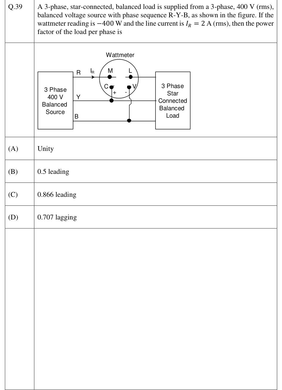
A 3-phase, star-connected, balanced load is supplied from a 3-phase, 400 V (rms), balanced voltage source with phase sequence R-Y-B, as shown in the figure. If the wattmeter reading is and the line current is (rms), then the power factor of the load per phase is

GATE 2023 EE question 39: Left: a box labelled '3 Phase 400 V Balanced Source' with three output lines labelled R (top), Y (middle) and B (bottom).Tap to open full size
Figure from the GATE 2023 EE paper. It is part of the question.
Figure description

Left: a box labelled '3 Phase 400 V Balanced Source' with three output lines labelled R (top), Y (middle) and B (bottom). All three run right to a box labelled '3 Phase Star Connected Balanced Load'. A single wattmeter (a circle labelled 'Wattmeter') has four terminals: M and L (current coil) on top, and C (marked +) and V (marked -) on the bottom. The current coil is in series with line R. The line current I_R (arrow pointing right, from source to load) enters terminal M and leaves terminal L toward the load. The pressure coil's + terminal C connects down to line Y (junction dot on Y). Its - terminal V connects down to line B (junction dot on B), crossing line Y with a hop (no connection). So the current coil carries I_R and the pressure coil measures V_YB (Y positive relative to B).

  1. (A)

    Unity

  2. (B)

    0.5 leading

  3. (C)

    0.866 leading

  4. (D)

    0.707 lagging

Answer and solution
GATE 2023 EE Q.39: answer and solution

GATE 2023 EE Q.64

GATE 2023 · EEQ.64 · 2 marks · NAT

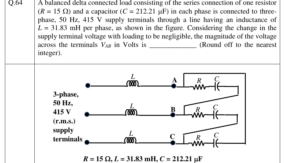
A balanced delta connected load consisting of the series connection of one resistor () and a capacitor () in each phase is connected to three-phase, 50 Hz, 415 V supply terminals through a line having an inductance of per phase, as shown in the figure. Considering the change in the supply terminal voltage with loading to be negligible, the magnitude of the voltage across the terminals in Volts is ________ (Round off to the nearest integer).

GATE 2023 EE question 64: Three supply terminals on the left, labelled '3-phase, 50 Hz, 415 V (r.m.s.) supply terminals'.Tap to open full size
Figure from the GATE 2023 EE paper. It is part of the question.
Figure description

Three supply terminals on the left, labelled '3-phase, 50 Hz, 415 V (r.m.s.) supply terminals'. Each supply terminal connects through a series line inductor L to a load terminal: top line to terminal A, middle line to terminal B, bottom line to terminal C. At the load, three identical branches, each a resistor R in series with a capacitor C, are connected in delta: one R-C branch between A and B, one between B and C, and one between C and A (the C-A branch is drawn with a return wire from the right side back up to A). Values printed below the figure: R = 15 Ω, L = 31.83 mH, C = 212.21 μF.

Answer and solution
GATE 2023 EE Q.64: answer and solution

GATE 2022 EE Q.21

GATE 2022 · EEQ.21 · 1 mark · MCQ

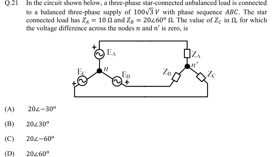
In the circuit shown below, a three-phase star-connected unbalanced load is connected to a balanced three-phase supply of with phase sequence . The star connected load has and . The value of in , for which the voltage difference across the nodes and is zero, is

GATE 2022 EE question 21: Left: a star-connected source with common node n (filled dot).Tap to open full size
Figure from the GATE 2022 EE paper. It is part of the question.
Figure description

Left: a star-connected source with common node n (filled dot). Three sinusoidal sources come out of n. E_A points straight up, with its + terminal at the top, away from n. E_C runs to the lower left, with its + terminal at the outer (lower-left) end. E_B runs to the lower right, with its + terminal at the outer (right) end. Right: a star-connected load with common node n' (filled dot). Z_A is a box above n', Z_B a box to the lower left of n', and Z_C a box to the lower right of n'. Wiring: a top wire joins the + end of E_A to the top of Z_A. A middle horizontal wire joins the + end of E_B to the outer end of Z_B. A bottom wire joins the + end of E_C to the outer end of Z_C. There is no wire between n and n' (three-wire system, floating load neutral).

  1. (A)

  2. (B)

  3. (C)

  4. (D)

Answer and solution
GATE 2022 EE Q.21: answer and solution

GATE 2022 EE Q.34

GATE 2022 · EEQ.34 · 1 mark · NAT

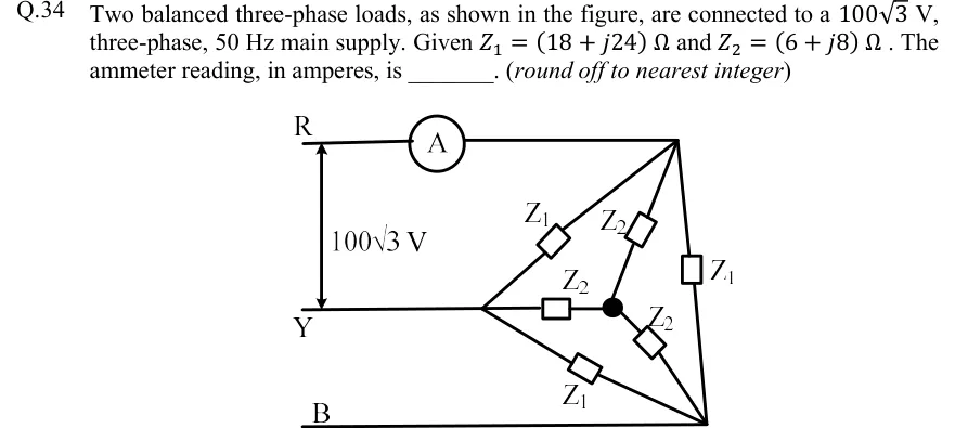
Two balanced three-phase loads, as shown in the figure, are connected to a V, three-phase, 50 Hz main supply. Given and . The ammeter reading, in amperes, is ________. (round off to nearest integer)

GATE 2022 EE question 34: Three supply lines R (top), Y (middle) and B (bottom);Tap to open full size
Figure from the GATE 2022 EE paper. It is part of the question.
Figure description

Three supply lines R (top), Y (middle) and B (bottom); the line voltage between R and Y is marked 100 √ 3 V with a double-headed arrow. Line R passes through an ammeter A and ends at a top-right load node. Line Y ends at a left load node. Line B ends at a bottom-right load node. Delta load: Z_1 between the Y node and the R node (upper diagonal), Z_1 between the R node and the B node (vertical right side), and Z_1 between the Y node and the B node (lower diagonal). Star load: a floating star point (solid dot, not connected to any neutral) inside the triangle, with Z_2 from the R node to the dot, Z_2 from the Y node to the dot (horizontal), and Z_2 from the dot to the B node. The ammeter therefore reads the total line current in R drawn by both loads.

Answer and solution
GATE 2022 EE Q.34: answer and solution

GATE 2022 IN Q.55

GATE 2022 · INQ.55 · 2 marks · NAT

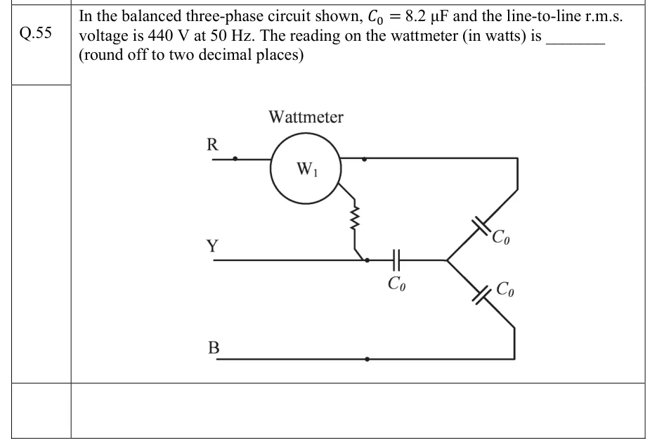
In the balanced three-phase circuit shown, and the line-to-line r.m.s. voltage is at . The reading on the wattmeter (in watts) is _______ (round off to two decimal places)

GATE 2022 IN question 55: Three supply lines labelled R (top), Y (middle) and B (bottom) enter from the left.Tap to open full size
Figure from the GATE 2022 IN paper. It is part of the question.
Figure description

Three supply lines labelled R (top), Y (middle) and B (bottom) enter from the left. Line R passes through the current coil of a wattmeter W1 (drawn as a circle labelled 'Wattmeter', 'W1') and continues right, then down to one capacitor C_0. The wattmeter's pressure-coil lead leaves the bottom of the circle and goes down through a series resistor (zig-zag) to a node on line Y, so the pressure coil sees V_RY and the current coil carries I_R. Line Y continues right through a capacitor C_0 to the star point. Line B runs right and then up to a third capacitor C_0. The three capacitors C_0 meet at a common star point (neutral not connected to the supply): a balanced star-connected purely capacitive load, one C_0 per phase.

Answer and solution
GATE 2022 IN Q.55: answer and solution

GATE 2020 IN Q.34

GATE 2020 · INQ.34 · 2 marks · NAT

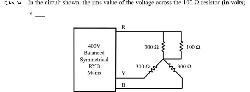
In the circuit shown, the rms value of the voltage across the 100 resistor (in volts) is ____.

GATE 2020 IN question 34: On the left, a box labelled "400V Balanced Symmetrical RYB Mains" with three output lines on its right side, labelled R…Tap to open full size
Figure from the GATE 2020 IN paper. It is part of the question.
Figure description

On the left, a box labelled "400V Balanced Symmetrical RYB Mains" with three output lines on its right side, labelled R (top), Y (middle) and B (bottom). There is no neutral wire. Line R runs horizontally to the right and connects to the top ends of two vertical resistors placed side by side: 300 Ω (left) and 100 Ω (right). The bottom ends of these two resistors are joined, so the 300 Ω and 100 Ω are in parallel, and this common bottom node connects to a star point. From the star point, a 300 Ω resistor runs diagonally down-left to line Y, and another 300 Ω resistor runs diagonally down-right to line B. The load is therefore an ungrounded star: R arm = 300 Ω ∥ 100 Ω, Y arm = 300 Ω, B arm = 300 Ω.

Answer and solution
GATE 2020 IN Q.34: answer and solution

GATE 2020 IN Q.42

GATE 2020 · INQ.42 · 2 marks · NAT

The real power drawn by a balanced load connected to a 400 V, 50 Hz, balanced, symmetrical 3-phase, 3-wire, RYB sequence mains is measured using the two-wattmeter method. Wattmeter is connected in the R line and wattmeter is connected in the B line. The line current is measured as A. If the wattmeter reads zero, the reading on (in watts) is ____

Answer and solution
See the question in the paper
GATE 2020 IN Q.42: answer and solution

GATE 2018 EE Q.47

GATE 2018 · EEQ.47 · 2 marks · NAT

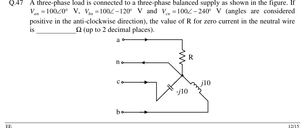
A three-phase load is connected to a three-phase balanced supply as shown in the figure. If , and (angles are considered positive in the anti-clockwise direction), the value of R for zero current in the neutral wire is ________ (up to 2 decimal places).

GATE 2018 EE question 47: Four supply terminals on the left, top to bottom: a, n, c, b.Tap to open full size
Figure from the GATE 2018 EE paper. It is part of the question.
Figure description

Four supply terminals on the left, top to bottom: a, n, c, b. The load is a star (Y) with one common star point (a solid dot). Line a: an arrow points right (into the load); the wire runs right, then down through a resistor R (vertical) to the star point. Neutral n: a wire from the star point runs up-left, then left to terminal n; its arrow points left (from load towards terminal n). Line c: an arrow points right; the wire runs right, down, then diagonally up-right through a capacitor labelled -j10 (ohms) to the star point. Line b: an arrow points right; the wire runs right, up, then diagonally up-left through an inductor labelled j10 (ohms) to the star point. So phase a has R, phase b has j10 (inductive) and phase c has -j10 (capacitive), all joined at the star point, which is tied to the supply neutral n.

Answer and solution
GATE 2018 EE Q.47: answer and solution

PRACTICE

5 questions to test yourself

PRACTICE 11 mark · MCQ

A balanced star-connected three-phase source has positive (abc) phase sequence and V (rms). The line voltage is

  1. (A)

    V

  2. (B)

    V

  3. (C)

    V

  4. (D)

    V

Answer and solution

Answer: (A)

  1. For abc, V and V.

  2. V.

  3. Direct check: V.

PRACTICE 21 mark · MCQ

Three identical impedances connected in star across a balanced three-phase supply absorb a total active power of 1.5 kW. If the same three impedances are reconnected in delta across the same supply, the total active power absorbed is

  1. (A)

    0.5 kW

  2. (B)

    1.5 kW

  3. (C)

    2.6 kW

  4. (D)

    4.5 kW

Answer and solution

Answer: (D)

  1. In star each impedance sees ; in delta it sees .

  2. Power in a fixed impedance is proportional to the square of its voltage, so each impedance absorbs times more.

  3. kW.

PRACTICE 31 mark · NAT

The total power of a balanced three-phase, three-wire load, supplied from a balanced sinusoidal three-phase source, is measured by the two-wattmeter method. One wattmeter reads 4 kW. The other deflects backwards, and after its current-coil connections are reversed it reads 1 kW. The power factor of the load is ______ (round off to three decimal places).

Answer and solution

Answer: (accepted range )

  1. The reversed meter's reading is negative: kW, kW.

  2. kW and kW.

  3. , so .

  4. pf (below 0.5, consistent with one negative reading). Check with the direct form: .

PRACTICE 42 marks · NAT

A balanced star-connected source of positive sequence, with phase voltage 230 V (rms), supplies a balanced delta-connected load of per phase through three lines, each of impedance . The total active power absorbed by the delta load, in W, is ______ (round off to the nearest integer).

Answer and solution

Answer: (accepted range )

  1. Star equivalent of the load: .

  2. Per-phase series impedance: , of magnitude .

  3. Line current: A.

  4. Load power: W W. Check with the delta phase current A: W. The line resistance's W is not part of the load power.

PRACTICE 52 marks · MSQ

The two-wattmeter method is used in a three-phase, three-wire system with balanced sinusoidal supply voltages. Which of the following statements is/are correct?

  1. (A)

    For a balanced load of power factor 0.5 lagging, one wattmeter reads zero.

  2. (B)

    For a balanced load of unity power factor, each wattmeter reads half the total active power.

  3. (C)

    For a balanced, purely inductive load, both wattmeters read zero.

  4. (D)

    The algebraic sum of the two readings equals the total active power only when the load is balanced.

Answer and solution

Answer: (A), (B)

  1. For a balanced load, and .

  2. A: gives . Correct.

  3. B: gives , and their sum is , so each is . Correct.

  4. C: gives and : equal and opposite, not zero (only their sum is zero). Incorrect.

  5. D: follows from KCL, , alone, so it holds for unbalanced three-wire loads too. Incorrect.

OFFICIAL GATE 2027 SYLLABUS WORDING

Copied from the GATE 2027 syllabus; see all 2027 syllabi.

GATE EE

balanced three phase circuits

Preparing in Kolkata? IAE Academy's course for GATE EE.