
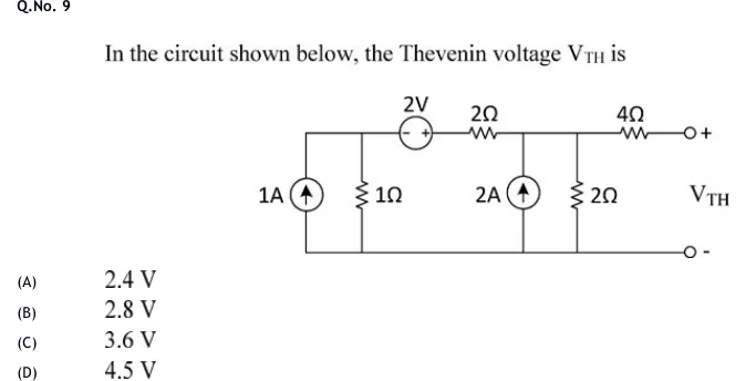
In the circuit shown below, the Thevenin voltage is
 Tap to open full size
Figure description
A ladder circuit with a common bottom (reference) rail. Left node A (top-left): a 1 A independent current source (arrow pointing up, i.e. current delivered into node A) and a 1 Ω resistor, both connected between node A and the bottom rail. From node A the top wire runs right through a 2 V independent voltage source (polarity marked '- +': negative terminal on the left/node-A side, positive terminal on the right) and then a 2 Ω series resistor to node B. At node B: a 2 A independent current source (arrow pointing up, current delivered into node B) and a 2 Ω resistor, both connected between node B and the bottom rail. From node B a 4 Ω series resistor runs right to the open output terminal marked '+'. The bottom rail extends right to the output terminal marked '-'. V_TH is the open-circuit voltage between the '+' and '-' terminals.
- (A)
2.4 V
- (B)
2.8 V
- (C)
3.6 V
- (D)
4.5 V