
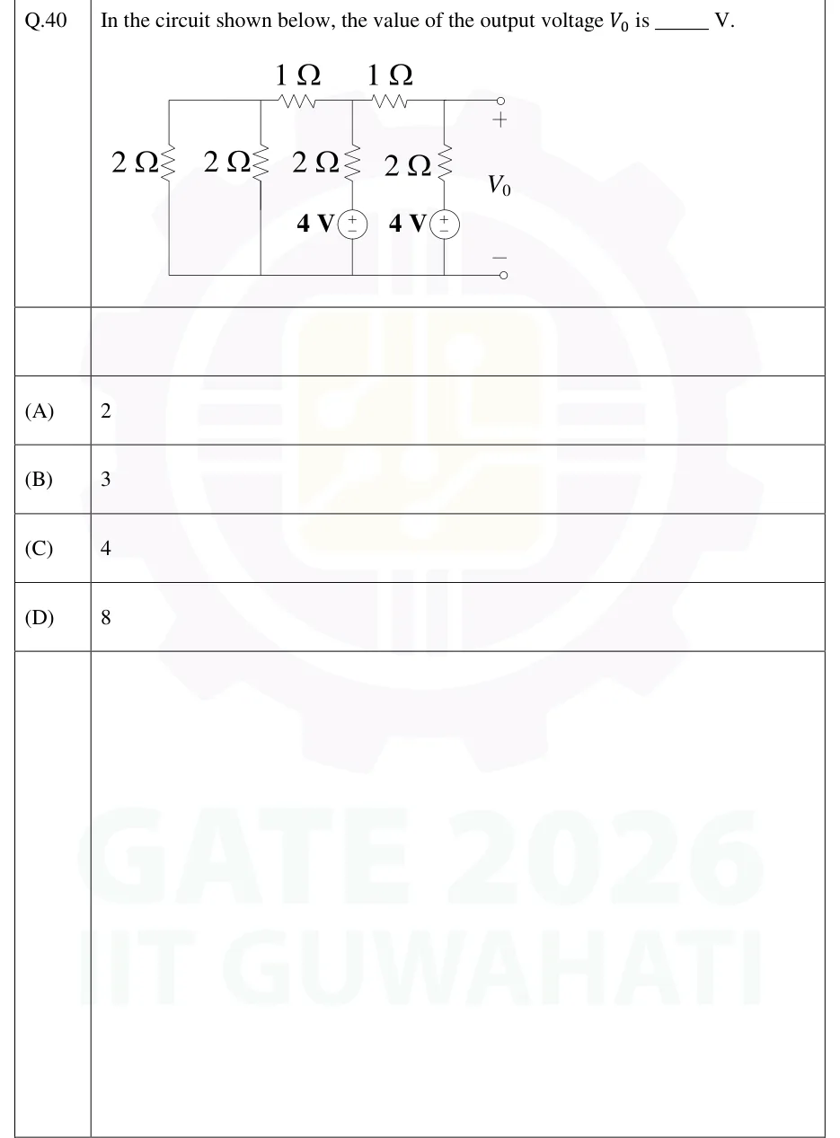
In the circuit shown below, the value of the output voltage is ______ V.
 Tap to open full size
Figure description
A ladder network between a top rail and a bottom (reference) rail, drawn left to right. The top rail runs from the far-left corner to a node A, then through a series 1 Ω resistor to node B, then through a second series 1 Ω resistor to node C, and from C by a plain wire to the output terminal marked +. The bottom rail is one plain wire that joins the foot of every vertical branch and ends at the output terminal marked −. Vertical branches, top rail to bottom rail, from left to right: (1) at the far left, a 2 Ω resistor (its top is joined to node A by plain wire); (2) at node A, a 2 Ω resistor; (3) at node B, a 2 Ω resistor in series with a 4 V DC source, + terminal upward (toward the resistor and node B), − terminal on the bottom rail; (4) at node C, a 2 Ω resistor in series with a 4 V DC source, + terminal upward, − terminal on the bottom rail. V_0 is the voltage from the + output terminal (node C) to the − output terminal (bottom rail).
- (A)
2
- (B)
3
- (C)
4
- (D)
8