
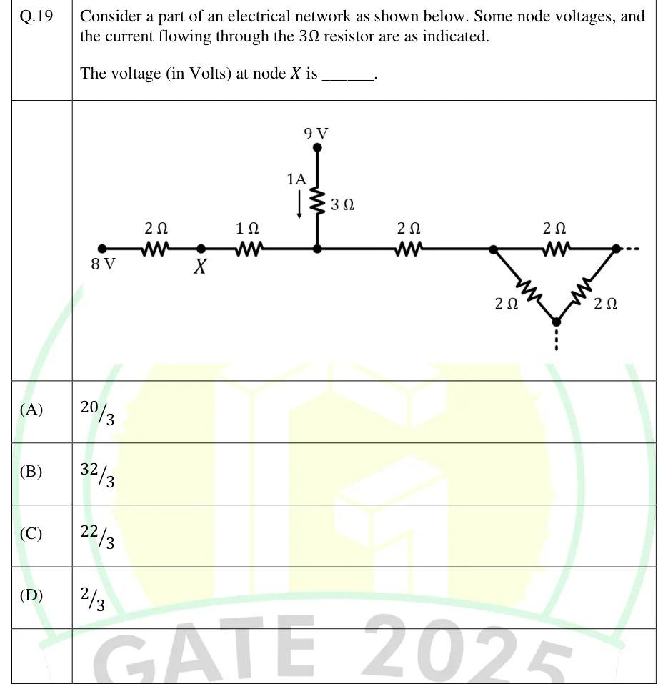
Consider a part of an electrical network as shown below. Some node voltages, and the current flowing through the resistor are as indicated.
The voltage (in Volts) at node is ______.
 Tap to open full size
Figure description
A horizontal chain of resistors running left to right. Leftmost node is marked 8 V. A 2 Ω resistor joins it to node X. A 1 Ω resistor joins X to an unlabelled junction node (call it N). From N, a 3 Ω resistor goes straight up to a node marked 9 V. An arrow labelled 1A beside the 3 Ω resistor points downward, so 1 A flows through the 3 Ω resistor from the 9 V node down into N. From N, another 2 Ω resistor goes to the right and ends at the left corner of a triangle (delta) made of three 2 Ω resistors: a top 2 Ω between the left and right corners, a 2 Ω from the left corner down to the bottom corner, and a 2 Ω from the right corner down to the bottom corner. A dotted line runs right from the right corner and down from the bottom corner, showing that the network continues and is not drawn. Node X connects only to the 2 Ω and the 1 Ω resistors.
- (A)
- (B)
- (C)
- (D)