
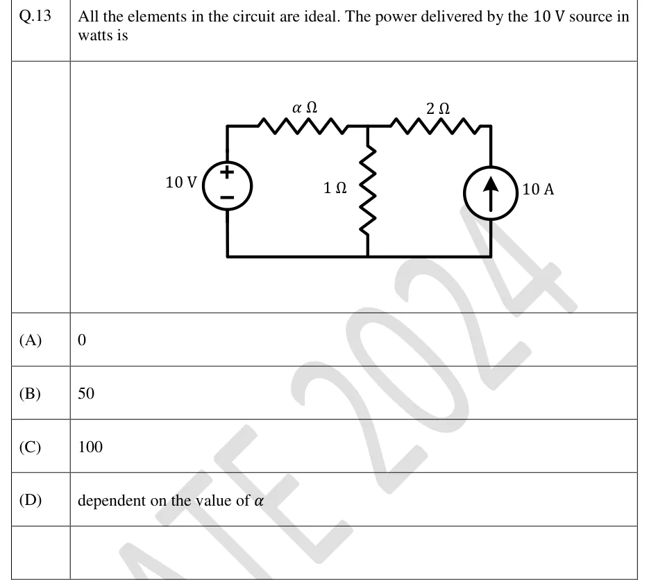
All the elements in the circuit are ideal. The power delivered by the source in watts is
 Tap to open full size
Figure description
Single-loop-pair circuit with a common bottom (reference) wire. Left branch: an ideal 10 V voltage source, + terminal at the top, - terminal at the bottom wire. From the top of the voltage source, a resistor of α Ω runs horizontally to a top middle node (call it A). A 1 Ω resistor connects node A vertically down to the bottom wire. From node A, a 2 Ω resistor runs horizontally to the top right node. Right branch: an ideal 10 A current source between the bottom wire and the top right node, arrow pointing upward (current delivered from the bottom wire into the top right node, i.e. towards the 2 Ω resistor and node A). The bottom wire joins the bottoms of the voltage source, the 1 Ω resistor and the current source.
- (A)
0
- (B)
50
- (C)
100
- (D)
dependent on the value of