
IAE Academy

GATE 2023 EE Q.32: solution and answer

GATE 2023 · EEQ.32 · 1 mark · NAT

For the circuit shown in the figure, , DC and , DC. The voltage in Volts is ________ (Round off to 1 decimal place).
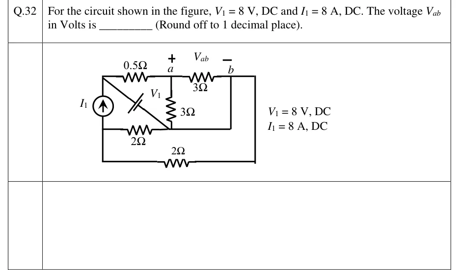
GATE 2023 EE question 32: A rectangular circuit with four distinct nodes.Tap to open full size
Figure from the GATE 2023 EE paper. It is part of the question.
Figure description

A rectangular circuit with four distinct nodes. Call the top-left corner P, the terminal on the top wire a, the terminal b, and the left-middle junction M. Top wire, left to right: P, a 0.5 Ω resistor, node a (marked +), a 3 Ω resistor, node b (marked −); V_ab is labelled across a (+) and b (−). From b the top wire carries on to the right-hand corner and down the right side to the bottom-right corner. Left side: the vertical wire from P down to M contains the current source I1, arrow pointing up, so it drives current from M up to P. Below M the left wire carries on to the bottom-left corner. A 2 Ω resistor on the bottom wire joins the bottom-left and bottom-right corners, so this 2 Ω sits between M and b. Middle horizontal wire: a 2 Ω resistor runs from M right to a junction N under node a. From N a plain wire runs right, then up a plain vertical wire to b, so N and b are the same node. A 3 Ω resistor hangs vertically from a down to N (= b). A diagonal from P down to N (= b) holds the DC voltage source V1, drawn as a battery. Its long plate (+) faces P and its short plate (−) faces N, so P is 8 V above b. The figure notes: V1 = 8 V, DC; I1 = 8 A, DC.

Answer and solution

ANSWER

.

Official answer: 5.9 to 6.1Source: Official answer key, GATE 2023 EE (IIT Kanpur)

  1. Simplify the topology first. The middle wire runs from the junction under straight across and up to with no element in it, so that junction and are one node. therefore sits directly between the top-left node and . Its long plate () faces , so .

  2. Combine the parallel elements. Both resistors join to , so . Both resistors join to , so together they are . Node touches only these resistors and , so the is in series with , making one branch from through to .

  3. An ideal voltage source holds its terminal voltage whatever current flows through it. The + branch is connected across (from to ), so it can only change the current in . stays at , and has no effect on . (Superposition gives the same result: with replaced by a short, and are one node, so circulates through the short and adds nothing to .)

  4. The only other path from to is the resistor in series with . Nothing else connects to , so the voltage divider rule applies:

  5. Check with KCL, taking , so and . The resistor carries from to , and this splits into through the two resistors ( each). At : arrives from , leaves through the , and the other leaves through into . At : comes in and returns to through the pair, so . KCL holds at every node, so .

KEY IDEA

An ideal voltage source fixes the voltage across its own terminals. Once you see that the junction under is wired straight to , sits directly across and . The branch (in series with the two resistors) is connected across , so it cannot change any voltage in the rest of the circuit. What is left is an source driving in series with , and the voltage divider rule gives .

WATCH OUT FOR

Missing the plain wire from the junction under to . A student who misses it treats the vertical , the middle and as meeting at a separate node and solves a much harder, wrong circuit. A second trap is letting push current through the divider: it only changes the current through the ideal source . Reading the battery backwards (long plate towards ) gives . The long plate is the positive terminal, and here it faces the top-left node.

From the GATE 2023 EE paper. Every question of this paper · Download the full paper · All 25 Laws & node/mesh questions, with notes

More Laws & node/mesh questions