
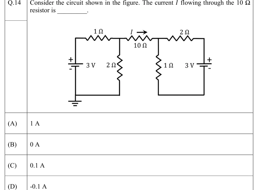
Consider the circuit shown in the figure. The current flowing through the resistor is ________.
 Tap to open full size
Figure description
Two sub-circuits joined by a single 10 Ω resistor. LEFT: a 3 V DC source drawn vertically, + terminal at top, - terminal at bottom; its bottom terminal sits on a bottom wire that is connected to a ground symbol. From the top (+) terminal a wire rises to a 1 Ω resistor in the top branch, running left to right to node A. From node A a 2 Ω resistor runs down to the same bottom (ground) wire, so the left loop is: 3 V source, 1 Ω, 2 Ω. RIGHT: node A connects through the 10 Ω resistor (horizontal, top branch) to node B; the current I is marked with an arrow pointing to the right (from A towards B) above the 10 Ω resistor. From node B a 1 Ω resistor runs down to a bottom wire on the right. From node B a 2 Ω resistor runs right along the top to the + (top) terminal of a second vertical 3 V DC source; its - (bottom) terminal connects to the right bottom wire, which returns to the bottom of the 1 Ω resistor. The right loop (2 Ω, 3 V source, 1 Ω) has its own bottom wire; it is NOT connected to the left bottom wire or to ground. The 10 Ω resistor is the only connection between the two loops.
- (A)
1 A
- (B)
0 A
- (C)
0.1 A
- (D)
-0.1 A