
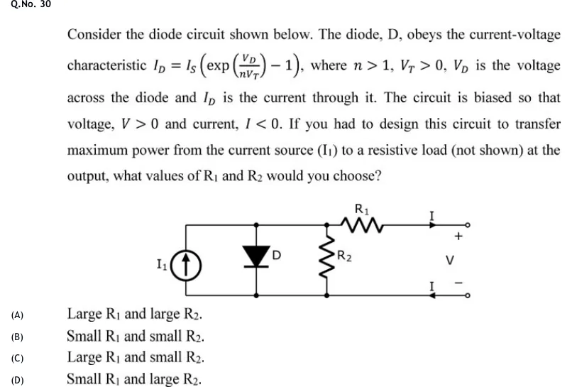
Consider the diode circuit shown below. The diode, D, obeys the current-voltage characteristic , where , , is the voltage across the diode and is the current through it. The circuit is biased so that voltage, and current, . If you had to design this circuit to transfer maximum power from the current source () to a resistive load (not shown) at the output, what values of and would you choose?
 Tap to open full size
Figure description
Two horizontal rails, top and bottom. From left to right, three elements are connected between the rails: (1) an independent current source I1 with its arrow pointing up, pushing current into the top rail; (2) diode D with the triangle pointing down, so the anode is on the top rail and the cathode is on the bottom rail; (3) resistor R2. Junction dots mark where D and R2 meet each rail. To the right of the R2 junction, resistor R1 sits in series in the top wire, which runs on to the upper output terminal (open circle). An arrow labelled I on the top wire, after R1, points right toward the upper terminal. An arrow labelled I on the bottom wire points left, from the lower terminal back into the circuit. The output voltage V is marked across the two terminals, + at the top and - at the bottom. The bottom rail runs straight to the lower terminal with no element in it.
- (A)
Large and large .
- (B)
Small and small .
- (C)
Large and small .
- (D)
Small and large .