IAE Academy

GATE IN

Sensing principles and signal conditioning

This topic covers how resistive, capacitive, inductive, piezoelectric, electromagnetic and Hall sensors turn a physical quantity into an electrical one, and the circuits (bridges, instrumentation amplifier, charge amplifier) that make that signal usable. Each formula below is given with the conditions under which it holds.

19 previous-year questions · 19 solved · 5 practice questions

Static characteristics of a sensor

A sensor converts a measurand (displacement, strain, force, speed, field) into an electrical output . The static characteristics describe the steady-state input-output relation, ignoring dynamics.

Term

Meaning

Sensitivity

Slope of the calibration curve, ; for a straight line it is constant

Linearity

How closely the curve follows a straight line; quoted as maximum deviation as a percentage of full-scale output

Hysteresis

Difference in output at the same input when approached from increasing and from decreasing values

Resolution

Smallest change in input that produces a detectable change in output

Range / span

Interval of input over which the specifications hold / its width

NON-LINEARITY

Delta y_max is the largest deviation of the actual output from the reference straight line.

Resistive sensors: potentiometer and strain gauge

A potentiometer gives output proportional to wiper position. If the meter or next stage draws current (load ), the output falls below the ideal value, which is the loading error. Let be the wiper position as a fraction of the full track (), measured from the grounded end.

LOADED POTENTIOMETER

R_p is the total track resistance. Reduces to x for R_L infinite. The error is zero at both ends. For R_L much larger than R_p: as a fraction of the ideal reading the error is about (R_p/R_L)x(1-x), largest at x = 0.5; as a fraction of V_s (full scale) it is about (R_p/R_L)x^2(1-x), largest at x = 2/3, where it is about 0.148 R_p/R_L.

A strain gauge changes resistance with strain . Starting from , a change in length, area and resistivity gives the gauge factor. Convention used here: , with tensile strain positive.

GAUGE FACTOR

nu is Poisson's ratio of the gauge material. 1 + 2nu is the dimensional effect; the last term is the piezoresistive effect. For metal foil gauges the resistivity term is small and G is about 2. Semiconductor gauges have G of order 100 or more, mainly from the piezoresistive term, but are more temperature-sensitive and less linear.

The Poisson effect: a specimen under tensile axial strain has transverse strain . A gauge mounted transversely therefore changes resistance by (relative), the opposite sign to an axial gauge. This neglects the gauge's own transverse sensitivity.

EXAM TIP

Temperature changes the resistance of every gauge, and also causes thermal expansion mismatch. A dummy gauge of the same type, on an unstrained piece of the same material at the same temperature, placed in the adjacent bridge arm cancels this, because equal changes in adjacent arms subtract.

Wheatstone bridge and strain-gauge outputs

Take a bridge with excitation and arms taken in order around the loop, initially all equal to : and are in series across the supply, and likewise, so and are opposite arms. For small changes, the output is the sum of the relative changes with alternating signs: adjacent arms of opposite sign add, adjacent arms of the same sign cancel.

EQUAL-ARM BRIDGE, SMALL CHANGES

Valid for all arms initially R and ΔR much less than R; sign of V_o depends on which terminals are taken as output.

Arrangement

Output (G = gauge factor, ε = strain)

Quarter bridge, one active gauge, exact

, about

Half bridge, two gauges in series across the supply (one divider) with equal and opposite changes ()

, exactly linear

Half bridge, axial gauge and transverse gauge (Poisson) in adjacent arms

Full bridge, four gauges, alternating

, exactly linear

Full bridge, axial gauges in opposite arms, transverse gauges in the other two opposite arms

QUARTER-BRIDGE NON-LINEARITY

Equal-arm bridge with one active arm; the fractional error is about (ΔR/R)/2. Half and full bridges with equal and opposite changes, each pair in series across the supply, have no such error; axial-plus-transverse arrangements keep a small one.

WORKED EXAMPLE

A quarter bridge with one gauge of and , other arms 350 Ω, is excited with V. The strain is 1000 microstrain. Find the exact output.

Solution
  1. .

  2. .

  3. V (the linear formula would give 5.250 mV, about 0.11 % high).

Answer: About 5.244 mV

WORKED EXAMPLE

A potentiometer with feeds a load . At mid-travel () find the output as a fraction of and the loading error as a percentage of the ideal reading.

Solution
  1. .

  2. Error of .

  3. Percentage of ideal reading (reading low).

Answer: ; error about −2.44 %

Instrumentation amplifier

A bridge output is a small differential signal riding on a large common-mode voltage (half the excitation, for a bridge supplied between and ground). The instrumentation amplifier amplifies the difference and rejects the common-mode part, with very high input resistance so the bridge is not loaded. The standard form is two input buffers with a shared gain resistor followed by a difference amplifier.

THREE-OP-AMP INSTRUMENTATION AMPLIFIER

Input-stage resistors R_1 (two equal), gain resistor R_g, difference stage with matched R_2 at the inputs and R_3 as feedback and ground resistors. Gain is set by R_g alone when R_3/R_2 is fixed.

EXAM TIP

Common-mode rejection of the difference stage depends on resistor matching. Gain in the first stage is applied only to the differential signal; the common-mode signal passes with gain 1, which is why this arrangement rejects common-mode better than a single difference amplifier of equal total gain.

Capacitive and inductive sensors, the LVDT

PARALLEL-PLATE CAPACITANCE

Fringing neglected. Sensing by varying plate gap d (output C is non-linear in d), overlap area A (linear in displacement), or dielectric (varying the effective ε_r).

For a single variable gap, , so the sensitivity rises as the gap shrinks. For an area-variation sensor with plate width and overlap length , and , a constant.

A variable-gap sensor is non-linear because . A differential arrangement uses a movable plate between two fixed plates at gap each, so and . For small the difference (with ), twice the change of a single gap, and the ratio of the difference to the sum is exactly linear.

DIFFERENTIAL VARIABLE-GAP CAPACITOR

Exactly linear in displacement x of the centre plate; needs a ratio-measuring circuit such as a bridge or ratiometric amplifier.

DIFFERENTIAL CAPACITOR IN A BRIDGE

C_1 and C_2 in series across the AC excitation V_s, the other half of the bridge two equal impedances, V_o measured across the detector diagonal by a high-impedance detector. The phase of V_o (0 or 180 degrees) shows the direction of x.

A variable-reluctance (inductive) sensor changes a coil's inductance by changing an air gap in its magnetic circuit.

VARIABLE-RELUCTANCE INDUCTANCE

N turns, l_g the total air-gap length, A_g the gap area; valid when the core's reluctance is negligible beside the gap's. L is then proportional to 1/l_g, so a single-gap sensor is non-linear; a differential (push-pull) pair in a bridge improves linearity, as for the capacitor.

The LVDT (linear variable differential transformer) has one primary driven by an AC voltage and two identical secondaries wound in series opposition around a movable ferromagnetic core. At the centre (null) the two secondary voltages are equal and cancel. Moving the core one way raises one secondary voltage and lowers the other, so the net output is proportional to displacement over the linear range.

  1. Output magnitude is proportional to the displacement from null within the linear range.

  2. On one side of null the output has one phase relative to the primary excitation; on the other side the phase is shifted by 180 degrees.

  3. The magnitude alone cannot tell direction; a phase-sensitive detector (demodulator) compares the output with the primary reference to give a DC output whose sign shows direction.

  4. At the null position a small residual voltage remains (the null voltage), due to harmonics and imperfect winding symmetry; it contains a quadrature component that the phase-sensitive detector rejects.

EXAM TIP

Beyond the linear range the LVDT output saturates and then falls. The excitation frequency should be well above the highest frequency of core motion (a common rule of thumb is at least ten times) so the output follows the displacement.

Piezoelectric sensors and the charge amplifier

A piezoelectric crystal generates a charge proportional to the applied force: , where is the charge sensitivity in C/N. Electrically it is a charge source in parallel with its own capacitance (and a very large leakage resistance). Connected through a cable of capacitance to an amplifier of input capacitance , the voltage seen depends on all the capacitances.

PIEZOELECTRIC VOLTAGE SENSITIVITY

t is the crystal thickness, p = F/A the applied stress; g in V·m/N. Follows from q = dF and C_p = ε_0 ε_r A/t, for an open-circuit crystal with no cable or amplifier load.

VOLTAGE-AMPLIFIER CONNECTION

Mid-band value, leakage neglected. Output changes if the cable is changed; this is the reason a charge amplifier is preferred.

With the leakage and amplifier input resistance in parallel with the total capacitance, the voltage-amplifier connection is also high-pass, with time constant .

IDEAL CHARGE AMPLIFIER

Op-amp with feedback capacitor C_f; independent of cable capacitance when the op-amp gain is high. Sign is inverting.

CHARGE AMPLIFIER WITH FINITE OP-AMP GAIN

A_ol is the op-amp's open-loop gain. When (1 + A_ol)C_f is much larger than C_t, V_o tends to −q/C_f, which is why the cable capacitance hardly matters.

CHARGE AMPLIFIER WITH FEEDBACK RESISTOR

R_f in parallel with C_f gives a high-pass response; at f_c the gain magnitude is 3 dB below its mid-band value 1/C_f. A steady (DC) force gives a charge that leaks away, so true static force cannot be measured.

EXAM TIP

Low-frequency limit: the time constant sets how long a step force can be tracked. A larger lowers the cut-off frequency. Piezoelectric sensors suit dynamic measurements (vibration, pressure pulses, impact), not static loads.

Electromagnetic (tachogenerator) and Hall-effect sensors

INDUCED EMF

Faraday's law for a coil of N turns linking flux Φ; Blv for a conductor of length l moving at speed v, with B, l and v mutually perpendicular. Electromagnetic velocity pickups and flowmeters use this principle.

A DC tachogenerator is a small generator whose output EMF is proportional to shaft angular speed, (SI: in rad/s); its polarity shows the direction of rotation, and ripple and brush effects are its main limitations. A drag-cup AC tachogenerator is excited at a fixed frequency and gives output at that frequency with amplitude proportional to speed; its phase relative to the excitation shows direction. A permanent-magnet AC tachogenerator gives output whose amplitude and frequency are both proportional to speed.

TOOTHED-WHEEL (VARIABLE-RELUCTANCE) TACHOMETER

A ferromagnetic wheel with T teeth turning at n rev/min past a magnetic pickup gives pulses at frequency f in Hz. The pulse amplitude also rises with speed, so the speed is read from the frequency.

In the Hall effect, a current through a thin conductor or semiconductor plate of thickness placed in a magnetic field perpendicular to the plate gives a transverse voltage.

HALL VOLTAGE

B perpendicular to the plate and to the current; n is carrier density, q the carrier charge magnitude, so this gives the magnitude of V_H. The sign of R_H follows the carrier sign (negative for electrons), which identifies the carrier type. V_H reverses sign when B (or I) is reversed. Semiconductors give a larger V_H than metals because n is much smaller.

EXAM TIP

A Hall sensor with constant measures magnetic flux density directly, and so also current (through the field it creates) and proximity of a magnet. The output is DC-responsive, so it works for static fields, unlike an induction coil.

PREVIOUS-YEAR QUESTIONS

19 questions from the IN papers

Try each question first, then open the answer. We placed each question under a topic ourselves; the exam paper does not label topics.

See these papers in full: GATE IN 2026 · GATE IN 2025 · GATE IN 2024 · GATE IN 2023 · GATE IN 2022 · GATE IN 2020 · GATE IN 2018

GATE 2026 IN Q.25

GATE 2026 · INQ.25 · 1 mark · MCQ

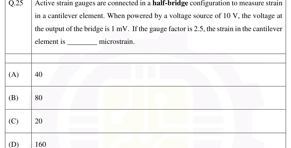
Active strain gauges are connected in a half-bridge configuration to measure strain in a cantilever element. When powered by a voltage source of 10 V, the voltage at the output of the bridge is 1 mV. If the gauge factor is 2.5, the strain in the cantilever element is ________ microstrain.

  1. (A)

    40

  2. (B)

    80

  3. (C)

    20

  4. (D)

    160

Answer and solution
See the question in the paper
GATE 2026 IN Q.25: answer and solution

GATE 2026 IN Q.50

GATE 2026 · INQ.50 · 2 marks · MCQ

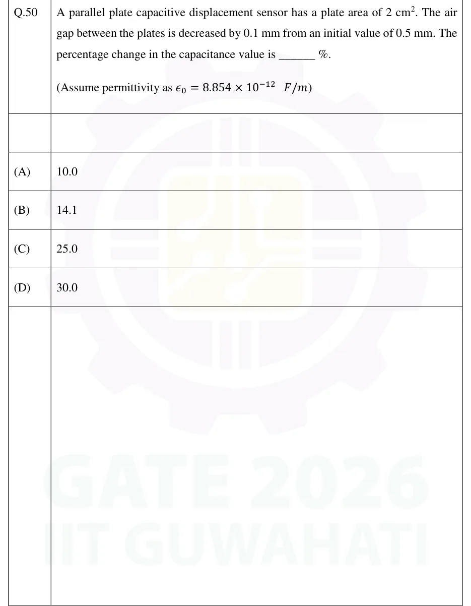
A parallel plate capacitive displacement sensor has a plate area of 2 cm. The air gap between the plates is decreased by 0.1 mm from an initial value of 0.5 mm. The percentage change in the capacitance value is ______ %. (Assume permittivity as F/m)

  1. (A)

    10.0

  2. (B)

    14.1

  3. (C)

    25.0

  4. (D)

    30.0

Answer and solution
See the question in the paper
GATE 2026 IN Q.50: answer and solution

GATE 2026 IN Q.63

GATE 2026 · INQ.63 · 2 marks · NAT

A current carrying semiconductor of thickness 0.7 mm is placed in a transverse magnetic field. The measured Hall voltage is 0.9 mV and the current is 6 mA. If the Hall coefficient is 4 x 10^-4 m^3/C, the value of the incident magnetic field is ______ T. (rounded off to two decimal places)

Answer and solution
See the question in the paper
GATE 2026 IN Q.63: answer and solution

GATE 2025 IN Q.13

GATE 2025 · INQ.13 · 1 mark · MCQ

The working of the hand-held metal detector most widely used by security personnel for human frisking is based on the principle of

  1. (A)

    change in reluctance of an iron core in presence of a metallic object

  2. (B)

    change in conductance of an iron core in presence of a metallic object

  3. (C)

    electric field induced by a metallic object

  4. (D)

    eddy current generation in a metallic object

Answer and solution
See the question in the paper
GATE 2025 IN Q.13: answer and solution

GATE 2025 IN Q.15

GATE 2025 · INQ.15 · 1 mark · MCQ

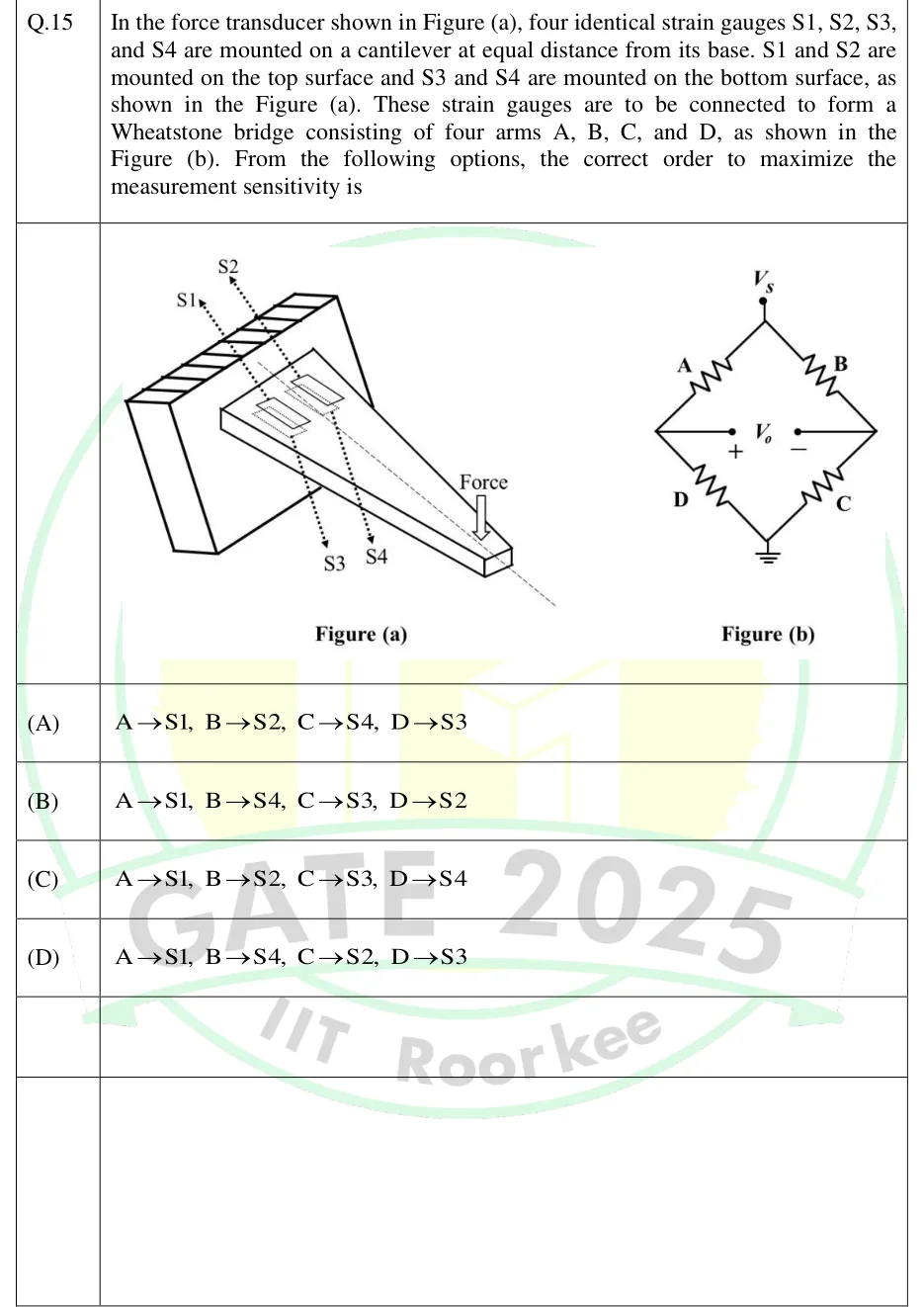
In the force transducer shown in Figure (a), four identical strain gauges S1, S2, S3, and S4 are mounted on a cantilever at equal distance from its base. S1 and S2 are mounted on the top surface and S3 and S4 are mounted on the bottom surface, as shown in the Figure (a). These strain gauges are to be connected to form a Wheatstone bridge consisting of four arms A, B, C, and D, as shown in the Figure (b). From the following options, the correct order to maximize the measurement sensitivity is

GATE 2025 IN question 15: Figure (a): a cantilever beam fixed to a wall at the left, extending to the right with a downward Force arrow at the free…Tap to open full size
Figure from the GATE 2025 IN paper. It is part of the question.
Figure description

Figure (a): a cantilever beam fixed to a wall at the left, extending to the right with a downward Force arrow at the free end. S1 and S2 are two strain gauges on the top surface near the fixed end, side by side, and S3 and S4 are on the bottom surface at the same positions (dotted lines run through to the underside). Figure (b): a Wheatstone bridge with excitation Vs at the top node and ground at the bottom node. Arm A is top-left, B is top-right, C is bottom-right and D is bottom-left. The output Vo is taken between the left node (A-D junction, marked +) and the right node (B-C junction, marked -).

  1. (A)

    A→S1, B→S2, C→S4, D→S3

  2. (B)

    A→S1, B→S4, C→S3, D→S2

  3. (C)

    A→S1, B→S2, C→S3, D→S4

  4. (D)

    A→S1, B→S4, C→S2, D→S3

Answer and solution
GATE 2025 IN Q.15: answer and solution

GATE 2025 IN Q.22

GATE 2025 · INQ.22 · 1 mark · MCQ

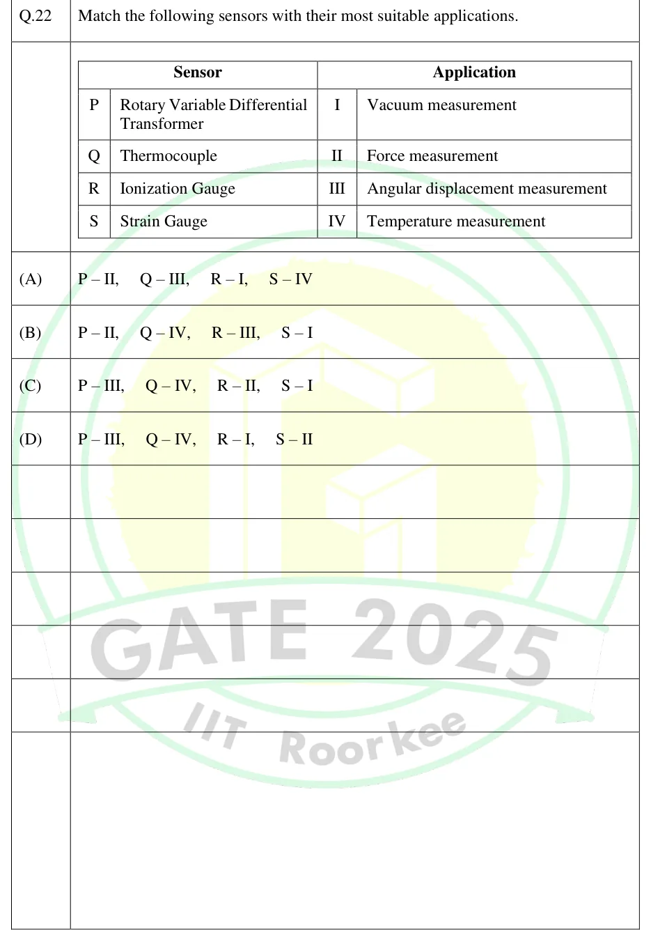
Match the following sensors with their most suitable applications.

Sensors: P Rotary Variable Differential Transformer; Q Thermocouple; R Ionization Gauge; S Strain Gauge.
Applications: I Vacuum measurement; II Force measurement; III Angular displacement measurement; IV Temperature measurement.

GATE 2025 IN question 22: A two-part table.Tap to open full size
Figure from the GATE 2025 IN paper. It is part of the question.
Figure description

A two-part table. The left part is headed 'Sensor' and lists P: Rotary Variable Differential Transformer, Q: Thermocouple, R: Ionization Gauge, S: Strain Gauge. The right part is headed 'Application' and lists I: Vacuum measurement, II: Force measurement, III: Angular displacement measurement, IV: Temperature measurement.

  1. (A)

    P – II, Q – III, R – I, S – IV

  2. (B)

    P – II, Q – IV, R – III, S – I

  3. (C)

    P – III, Q – IV, R – II, S – I

  4. (D)

    P – III, Q – IV, R – I, S – II

Answer and solution
GATE 2025 IN Q.22: answer and solution

GATE 2025 IN Q.53

GATE 2025 · INQ.53 · 2 marks · NAT

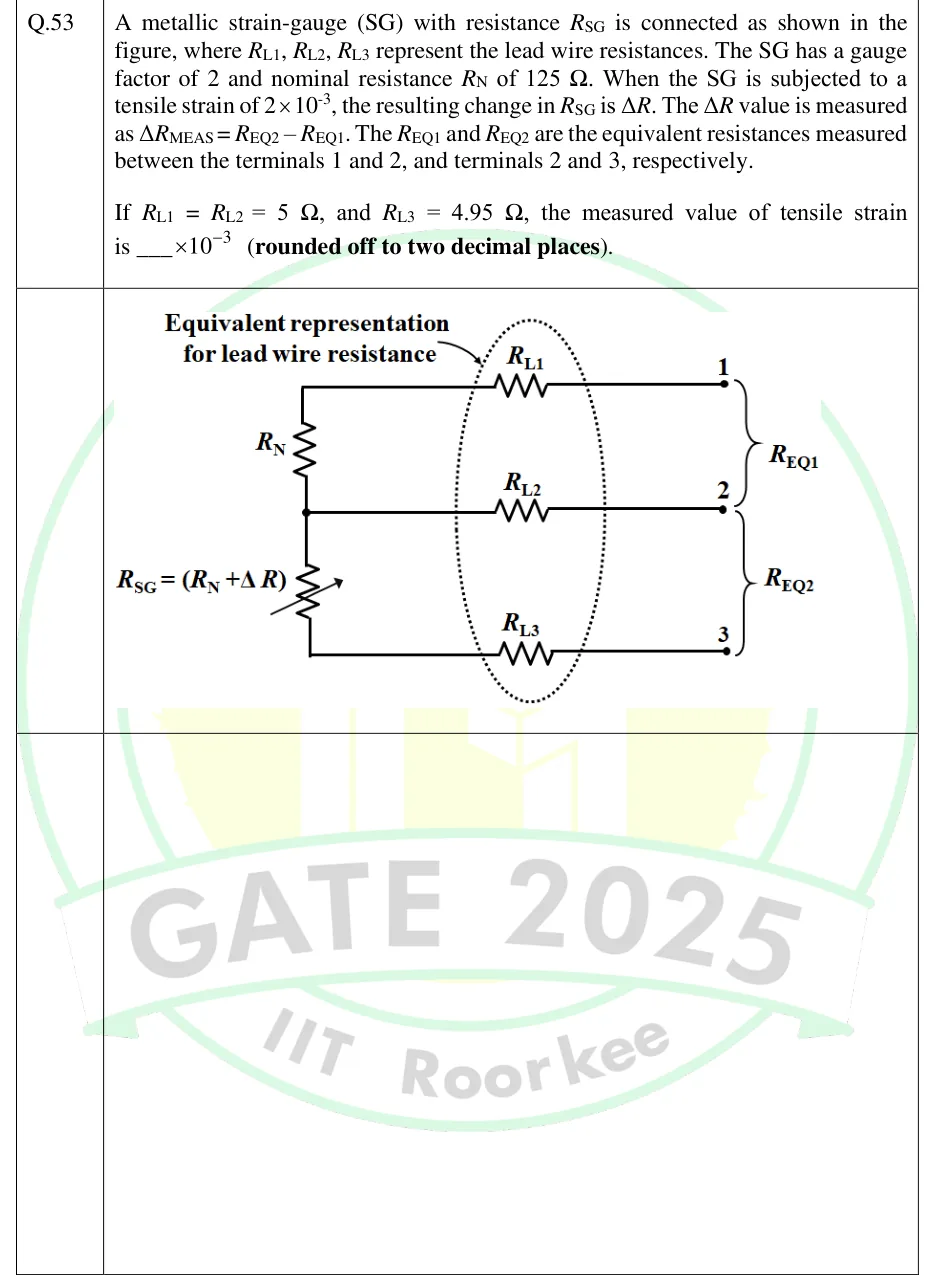
A metallic strain-gauge (SG) with resistance is connected as shown in the figure, where , , represent the lead wire resistances. The SG has a gauge factor of 2 and nominal resistance of 125 . When the SG is subjected to a tensile strain of , the resulting change in is . The value is measured as . The and are the equivalent resistances measured between the terminals 1 and 2, and terminals 2 and 3, respectively. If and , the measured value of tensile strain is ___ (rounded off to two decimal places).

GATE 2025 IN question 53: Three-wire strain gauge connection.Tap to open full size
Figure from the GATE 2025 IN paper. It is part of the question.
Figure description

Three-wire strain gauge connection. Fixed resistor R_N sits above the strain gauge R_SG = (R_N + ΔR), drawn as a variable resistor, in series on the left. The top end of R_N goes through lead resistance R_L1 to terminal 1. The junction between R_N and R_SG goes through R_L2 to terminal 2. The bottom end of R_SG goes through R_L3 to terminal 3. A dotted ellipse around R_L1, R_L2 and R_L3 is labelled 'Equivalent representation for lead wire resistance'. Brace R_EQ1 spans terminals 1 and 2, and brace R_EQ2 spans terminals 2 and 3.

Answer and solution
GATE 2025 IN Q.53: answer and solution

GATE 2024 IN Q.14

GATE 2024 · INQ.14 · 1 mark · MCQ

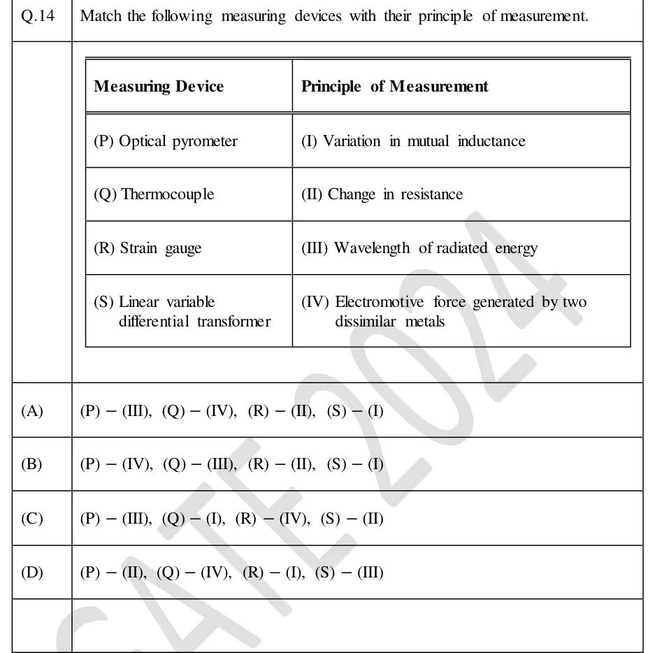
Match the following measuring devices with their principle of measurement.

Measuring Device: (P) Optical pyrometer; (Q) Thermocouple; (R) Strain gauge; (S) Linear variable differential transformer.
Principle of Measurement: (I) Variation in mutual inductance; (II) Change in resistance; (III) Wavelength of radiated energy; (IV) Electromotive force generated by two dissimilar metals.

GATE 2024 IN question 14: A two-column table.Tap to open full size
Figure from the GATE 2024 IN paper. It is part of the question.
Figure description

A two-column table. Left column 'Measuring Device' lists (P) Optical pyrometer, (Q) Thermocouple, (R) Strain gauge, (S) Linear variable differential transformer. Right column 'Principle of Measurement' lists (I) Variation in mutual inductance, (II) Change in resistance, (III) Wavelength of radiated energy, (IV) Electromotive force generated by two dissimilar metals.

  1. (A)

    (P) − (III), (Q) − (IV), (R) − (II), (S) − (I)

  2. (B)

    (P) − (IV), (Q) − (III), (R) − (II), (S) − (I)

  3. (C)

    (P) − (III), (Q) − (I), (R) − (IV), (S) − (II)

  4. (D)

    (P) − (II), (Q) − (IV), (R) − (I), (S) − (III)

Answer and solution
GATE 2024 IN Q.14: answer and solution

GATE 2024 IN Q.32

GATE 2024 · INQ.32 · 1 mark · NAT

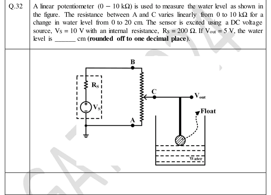
A linear potentiometer (0 − 10 kΩ) is used to measure the water level as shown in the figure. The resistance between A and C varies linearly from 0 to 10 kΩ for a change in water level from 0 to 20 cm. The sensor is excited using a DC voltage source, V_S = 10 V with an internal resistance, R_S = 200 Ω. If V_out = 5 V, the water level is ______ cm (rounded off to one decimal place).

GATE 2024 IN question 32: A DC source V_S (positive terminal up) in series with a dashed-box internal resistance R_S.Tap to open full size
Figure from the GATE 2024 IN paper. It is part of the question.
Figure description

A DC source V_S (positive terminal up) in series with a dashed-box internal resistance R_S. The top of this branch goes to terminal B (top end of the potentiometer); the bottom goes to ground and to terminal A (bottom end of the potentiometer). The potentiometer is a vertical resistor between B (top) and A (bottom) with a wiper C. The wiper is mechanically linked by a rod to a float resting on the water surface in a tank. V_out is taken at the wiper C with respect to ground (A), and the output is unloaded.

Answer and solution
GATE 2024 IN Q.32: answer and solution

GATE 2023 IN Q.14

GATE 2023 · INQ.14 · 1 mark · MCQ

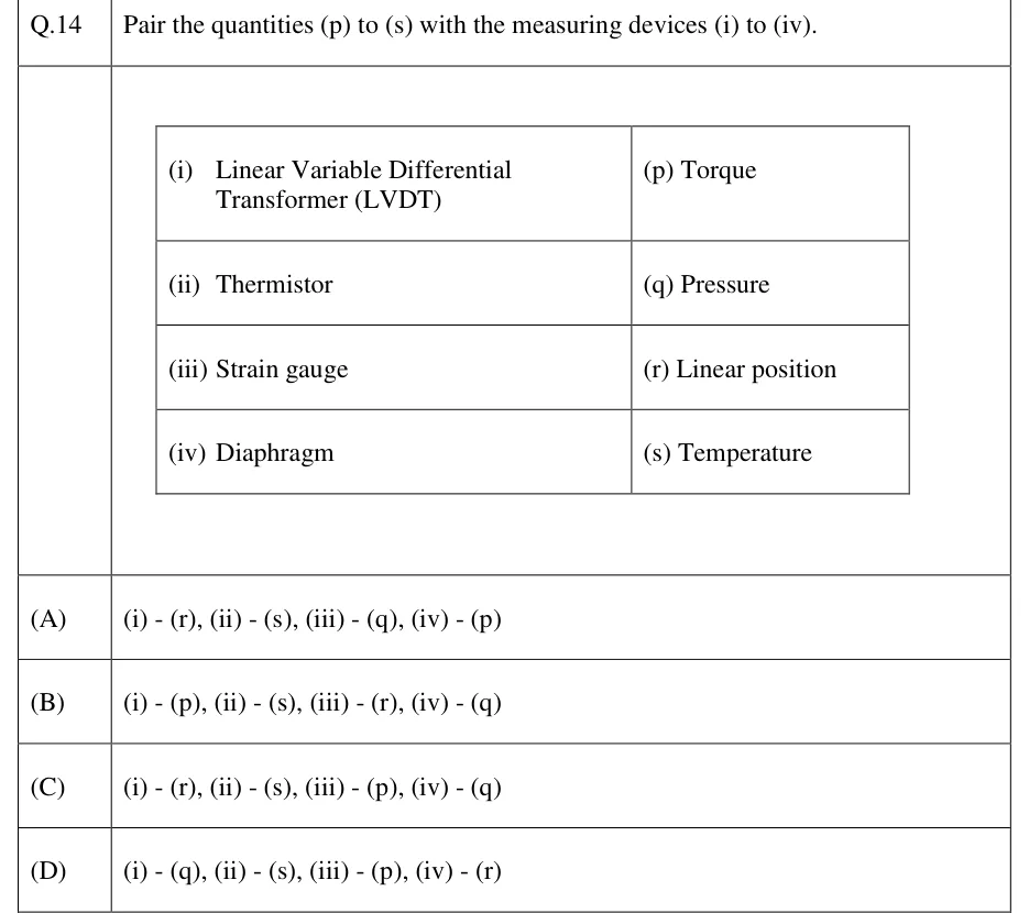
Pair the quantities (p) to (s) with the measuring devices (i) to (iv).

Devices: (i) Linear Variable Differential Transformer (LVDT); (ii) Thermistor; (iii) Strain gauge; (iv) Diaphragm.
Quantities: (p) Torque; (q) Pressure; (r) Linear position; (s) Temperature.

GATE 2023 IN question 14: A two-column table.Tap to open full size
Figure from the GATE 2023 IN paper. It is part of the question.
Figure description

A two-column table. Left column: (i) Linear Variable Differential Transformer (LVDT), (ii) Thermistor, (iii) Strain gauge, (iv) Diaphragm. Right column, in the same rows: (p) Torque, (q) Pressure, (r) Linear position, (s) Temperature. The rows are not matched; the task is to pair them.

  1. (A)

    (i) - (r), (ii) - (s), (iii) - (q), (iv) - (p)

  2. (B)

    (i) - (p), (ii) - (s), (iii) - (r), (iv) - (q)

  3. (C)

    (i) - (r), (ii) - (s), (iii) - (p), (iv) - (q)

  4. (D)

    (i) - (q), (ii) - (s), (iii) - (p), (iv) - (r)

Answer and solution
GATE 2023 IN Q.14: answer and solution
Show the other 9 questions

GATE 2023 IN Q.51

GATE 2023 · INQ.51 · 2 marks · NAT

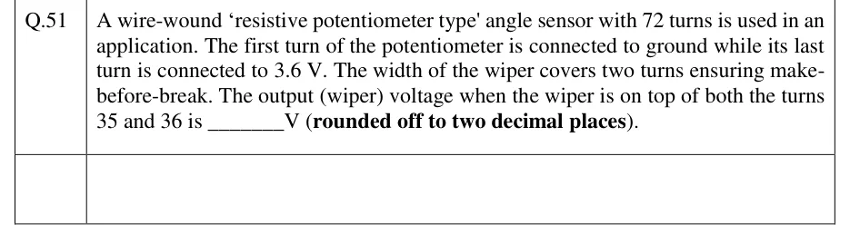
A wire-wound 'resistive potentiometer type' angle sensor with 72 turns is used in an application. The first turn of the potentiometer is connected to ground while its last turn is connected to 3.6 V. The width of the wiper covers two turns ensuring make-before-break. The output (wiper) voltage when the wiper is on top of both the turns 35 and 36 is ______ V (rounded off to two decimal places).

Answer and solution
See the question in the paper
GATE 2023 IN Q.51: answer and solution

GATE 2023 IN Q.52

GATE 2023 · INQ.52 · 2 marks · NAT

The two secondaries of a linear variable differential transformer (LVDT) showed a magnitude of 2 V (RMS) for zero displacement position of the core. It is noted that the phase of one of the secondaries has a deviation of one degree from the expected phase. Other than this deviation, the LVDT is ideal.

If the differential output sensitivity of the LVDT is 1 mV (RMS)/1 µm, the output for zero displacement is __________ µm (rounded off to one decimal place).

Answer and solution
See the question in the paper
GATE 2023 IN Q.52: answer and solution

GATE 2023 IN Q.54

GATE 2023 · INQ.54 · 2 marks · NAT

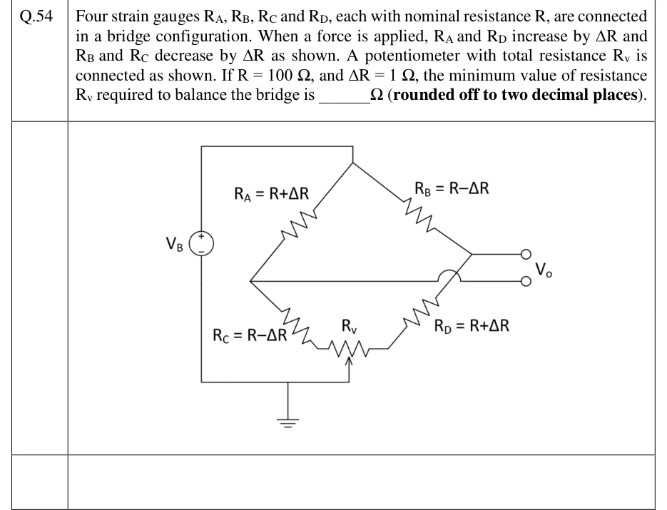
Four strain gauges R_A, R_B, R_C and R_D, each with nominal resistance R, are connected in a bridge configuration. When a force is applied, R_A and R_D increase by ΔR and R_B and R_C decrease by ΔR as shown. A potentiometer with total resistance R_v is connected as shown. If R = 100 Ω, and ΔR = 1 Ω, the minimum value of resistance R_v required to balance the bridge is ______ Ω (rounded off to two decimal places).

GATE 2023 IN question 54: Wheatstone bridge excited by source V_B (plus terminal up) across the top node and ground.Tap to open full size
Figure from the GATE 2023 IN paper. It is part of the question.
Figure description

Wheatstone bridge excited by source V_B (plus terminal up) across the top node and ground. Left arm: R_A = R+ΔR from the top node to the left node, then R_C = R−ΔR from the left node down to the left end of the potentiometer R_v. Right arm: R_B = R−ΔR from the top node to the right node, then R_D = R+ΔR from the right node down to the right end of the potentiometer R_v. The potentiometer's wiper (arrow) is connected to ground, which is also the negative side of V_B. The output V_o is taken between the left node and the right node (the wire from the left node runs horizontally and jumps over the R_D wire to the lower output terminal).

Answer and solution
GATE 2023 IN Q.54: answer and solution

GATE 2020 IN Q.10

GATE 2020 · INQ.10 · 1 mark · MCQ

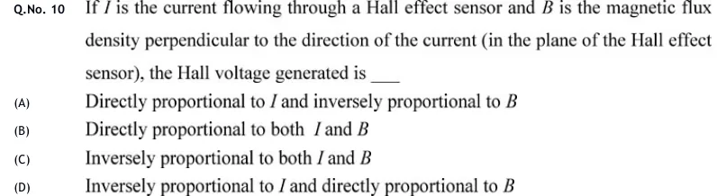
If is the current flowing through a Hall effect sensor and is the magnetic flux density perpendicular to the direction of the current (in the plane of the Hall effect sensor), the Hall voltage generated is ____

  1. (A)

    Directly proportional to and inversely proportional to

  2. (B)

    Directly proportional to both and

  3. (C)

    Inversely proportional to both and

  4. (D)

    Inversely proportional to and directly proportional to

Answer and solution
See the question in the paper
GATE 2020 IN Q.10: answer and solution

GATE 2020 IN Q.24

GATE 2020 · INQ.24 · 1 mark · NAT

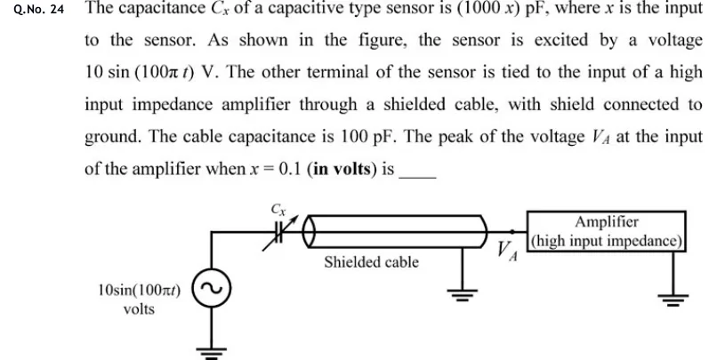
The capacitance of a capacitive type sensor is pF, where is the input to the sensor. As shown in the figure, the sensor is excited by a voltage V. The other terminal of the sensor is tied to the input of a high input impedance amplifier through a shielded cable, with shield connected to ground. The cable capacitance is 100 pF. The peak of the voltage at the input of the amplifier when (in volts) is ____

GATE 2020 IN question 24: A sinusoidal source 10 sin(100 pi t) volts has one terminal grounded and the other connected to one plate of the variable…Tap to open full size
Figure from the GATE 2020 IN paper. It is part of the question.
Figure description

A sinusoidal source 10 sin(100 pi t) volts has one terminal grounded and the other connected to one plate of the variable capacitor C_x (drawn with an arrow through it). The other plate of C_x connects to the inner conductor of a shielded cable, drawn as a cylinder whose shield is connected to ground. The far end of the cable joins node V_A, the input of a box labelled 'Amplifier (high input impedance)', whose other terminal is grounded.

Answer and solution
GATE 2020 IN Q.24: answer and solution

GATE 2020 IN Q.45

GATE 2020 · INQ.45 · 2 marks · NAT

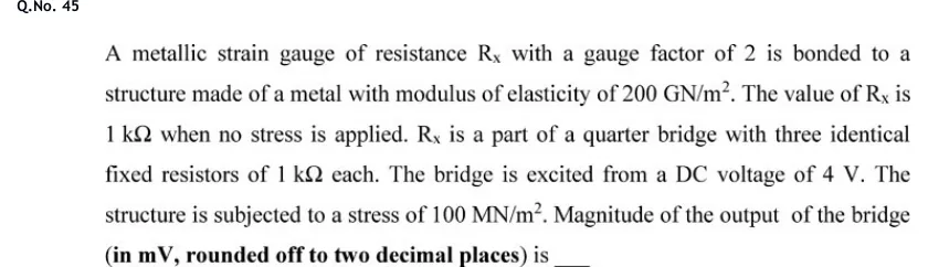
A metallic strain gauge of resistance with a gauge factor of 2 is bonded to a structure made of a metal with modulus of elasticity of 200 GN/m. The value of is 1 k when no stress is applied. is a part of a quarter bridge with three identical fixed resistors of 1 k each. The bridge is excited from a DC voltage of 4 V. The structure is subjected to a stress of 100 MN/m. Magnitude of the output of the bridge (in mV, rounded off to two decimal places) is ____

Answer and solution
See the question in the paper
GATE 2020 IN Q.45: answer and solution

GATE 2018 IN Q.51

GATE 2018 · INQ.51 · 2 marks · NAT

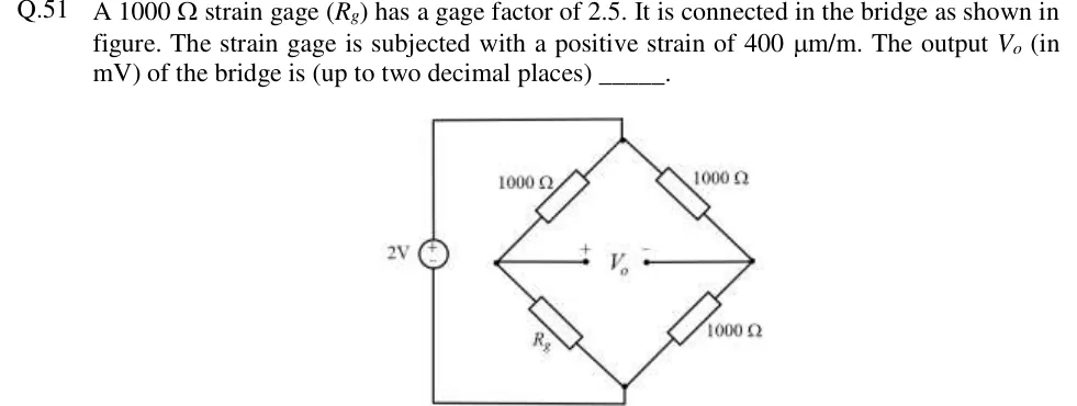
A 1000 strain gage () has a gage factor of 2.5. It is connected in the bridge as shown in figure. The strain gage is subjected with a positive strain of 400 m/m. The output (in mV) of the bridge is (up to two decimal places) ______.

GATE 2018 IN question 51: Wheatstone bridge in diamond form excited by a 2 V source.Tap to open full size
Figure from the GATE 2018 IN paper. It is part of the question.
Figure description

Wheatstone bridge in diamond form excited by a 2 V source. The source's + terminal is at the top node and its other terminal at the bottom node, joined by wires down the left side. Top-left arm: 1000 ohm, from the top node to the left middle node. Top-right arm: 1000 ohm, from the top node to the right middle node. Bottom-left arm: strain gage R_g, from the left middle node to the bottom node. Bottom-right arm: 1000 ohm, from the right middle node to the bottom node. The output V_o is measured between the left middle node (+) and the right middle node (-).

Answer and solution
GATE 2018 IN Q.51: answer and solution

PRACTICE

5 questions to test yourself

PRACTICE 11 mark · NAT

A piezoelectric sensor is connected to a charge amplifier whose feedback is in parallel with . Find the lower cut-off (-3 dB) frequency in Hz.

Answer and solution

Answer: (accepted range )

  1. s.

  2. Hz.

PRACTICE 22 marks · MCQ

A full bridge has four identical strain gauges with bonded on a bar under tension: two along the axis, placed in opposite arms, and two transversely, placed in the other two opposite arms. Poisson's ratio is , the strain is 500 microstrain and V. The output is approximately

  1. (A)

    3.25 mV

  2. (B)

    5.0 mV

  3. (C)

    6.5 mV

  4. (D)

    10.0 mV

Answer and solution

Answer: (C)

  1. Axial gauges: ; transverse gauges: . Opposite arms add, so .

  2. V.

  3. 6.5 mV, option C.

PRACTICE 32 marks · NAT

A potentiometer of total resistance is supplied with V and loaded by . With the wiper at 60 % of full travel (measured from the grounded end), find the output voltage in volts.

Answer and solution

Answer: (accepted range )

  1. , .

  2. .

  3. V.

PRACTICE 41 mark · MCQ

A quarter bridge (equal arms, one active gauge) has . The exact output is lower than the linear estimate by about

  1. (A)

    0.5 %

  2. (B)

    1 %

  3. (C)

    2 %

  4. (D)

    4 %

Answer and solution

Answer: (B)

  1. Exact/linear .

  2. Shortfall , about 1 %.

  3. Option B.

PRACTICE 52 marks · MSQ

Which of the following statements are correct?

  1. (A)

    For a differential variable-gap capacitive sensor, is linear in displacement.

  2. (B)

    A charge amplifier with a finite feedback resistor can measure a constant static force indefinitely.

  3. (C)

    The Hall voltage reverses sign if the direction of the magnetic field is reversed with the current unchanged.

  4. (D)

    The LVDT output for core displacements on opposite sides of null is in phase for both.

Answer and solution

Answer: (A), (C)

  1. A is true: the ratio equals .

  2. B is false: the feedback resistor makes the amplifier a high-pass system; a constant charge leaks away.

  3. C is true since .

  4. D is false: the two sides give outputs 180 degrees out of phase.

OFFICIAL GATE 2027 SYLLABUS WORDING

Copied from the GATE 2027 syllabus; see all 2027 syllabi.

GATE IN

Resistive, capacitive, inductive, piezoelectric, electromagnetic and Hall effect sensors and associated signal conditioning circuits

Preparing in Kolkata? IAE Academy's course for GATE IN.