
IAE Academy

GATE IN

Instrument networks and the 4-20 mA transmitter

The 4-20 mA two-wire current loop carries a measured value as a current that is the same at every point of the series loop. As long as the supply can still drive the loop, cable resistance does not change the reading, and the current signal resists picked-up noise. This topic covers scaling a measured value to a loop current and back, checking the supply against the loop resistance, transmitter wiring, and how analog, HART, fieldbus and wireless links compare.

1 previous-year question · 1 solved · 5 practice questions

The 4-20 mA current loop and why it is used

A transmitter converts a sensor output (pressure, temperature, flow) into a current between 4 mA and 20 mA. The transmitter is placed in series with a DC supply and a receiver (a resistor, indicator, controller input or data-acquisition input). Because the loop is a single series circuit, the same current flows through every element, whatever the cable resistance, as long as the supply can still drive the loop.

Convention used here: 4 mA corresponds to the lower range value (0 % of span) and 20 mA to the upper range value (100 % of span). The non-zero 4 mA is called the live zero.

  1. Live zero: a reading of 0 mA, or any current well below 4 mA, cannot be a valid measurement, so it signals a broken wire, a failed supply or a dead transmitter. A true 0 % reading is 4 mA, so a fault and a zero reading are never confused.

  2. Fault levels: a common convention treats 3.8 mA to 20.5 mA as the measuring range (slight under-range and over-range allowed). A current at or below 3.6 mA, or at or above 21 mA, is used to signal a transmitter fault.

  3. Power over the same wires: the transmitter's own circuit runs on less than 4 mA drawn from the loop, so only two wires are needed for both power and signal (the two-wire transmitter).

  4. Noise rejection: the signal is a current, so series voltage drops in the cable (lead resistance, contact resistance) do not change it. A low-impedance receiver (for example 250 Ω) also keeps the voltage produced by a coupled noise current small. Twisted-pair cable reduces magnetically induced noise, and a shield reduces capacitively coupled noise.

  5. Long distances: accuracy is not lost with cable length as long as the supply can still drive the full loop (see the compliance check).

Connection

Wires

Power for the transmitter

Transmitter consumption

Two-wire (loop-powered)

2: power and signal share the same pair

From the loop current itself

Must stay below 4 mA

Three-wire

3: supply, signal, common return

Separate supply, sharing a common return with the signal

Not limited by the loop current

Four-wire

4: one pair for power, one pair for signal

Separate supply (often mains or a separate DC supply)

Not limited by the loop current

EXAM TIP

Do not say that the loop 'eliminates' lead resistance in every case. The current is independent of the loop resistance only while the supply is large enough for the transmitter to keep regulating (compliance). Beyond that limit, the current can no longer reach 20 mA.

Scaling between the measured value and the loop current

Let the transmitter be calibrated so that the lower range value (LRV) gives 4 mA and the upper range value (URV) gives 20 mA, with a linear relation between them. The span is URV minus LRV.

MEASURED VALUE TO LOOP CURRENT

Linear transmitter, 4 mA at LRV and 20 mA at URV; I in mA.

LOOP CURRENT TO MEASURED VALUE

Inverse of the relation above; valid for 4 mA to 20 mA.

PERCENT OF SPAN FROM CURRENT

0 % at 4 mA, 50 % at 12 mA, 100 % at 20 mA.

RECEIVER VOLTAGE

A 250 Ω receiver turns 4 mA to 20 mA into 1 V to 5 V.

WORKED EXAMPLE

A temperature transmitter is calibrated for 100 °C to 300 °C with a 4-20 mA output. (a) Find the current at 175 °C. (b) Find the temperature when the loop current is 14 mA.

Solution
  1. Span = 300 − 100 = 200 °C.

  2. (a) Fraction = (175 − 100)/200 = 0.375, so I = 4 + 16 × 0.375 = 4 + 6 = 10 mA.

  3. (b) Fraction = (14 − 4)/16 = 0.625, so T = 100 + 0.625 × 200 = 225 °C.

Answer: (a) 10 mA; (b) 225 °C.

EXAM TIP

The formulas work unchanged when the LRV is negative, for example a range of −20 kPa to 80 kPa: enter the LRV with its sign. Here 0 kPa gives mA.

EXAM TIP

If the question says the transmitter is not linearised (for example a differential-pressure flow transmitter with no square-root extractor), the current is linear in the differential pressure, not in the flow. Convert current to differential pressure first, then apply the flow law.

Loop power budget: supply, resistance and compliance

The transmitter needs a minimum terminal voltage to work (its minimum operating voltage). The rest of the supply voltage is available to drive current through the loop resistance. The largest drop occurs at the largest current, taken as 20 mA unless the question gives an over-range value.

SUPPLY VOLTAGE REQUIREMENT

I_max = 20 mA unless an over-range current is stated; all series resistances are included.

MAXIMUM TOTAL LOOP RESISTANCE

R_L is wire plus receiver resistance in series; with V in volts and I in amperes, R is in ohms.

  1. Write the loop as one series circuit: supply, transmitter, wire, receiver(s).

  2. Use the largest current (20 mA) to find the largest drop across the series resistances.

  3. Subtract that drop and the transmitter's minimum voltage from the supply, or compare the supply with their sum.

  4. Several receivers in series add their resistances; the same current flows through each.

  5. Cable resistance counts both conductors: a cable of length L with resistance r per unit length per conductor adds 2rL.

WORKED EXAMPLE

A loop uses a 24 V supply. The transmitter needs at least 12 V at its terminals. The cable has a total resistance of 100 Ω (both wires). What is the largest receiver resistance that keeps the loop working up to 20 mA, and what voltage does a 250 Ω receiver show at 12 mA?

Solution
  1. Voltage available for wire and receiver = 24 − 12 = 12 V.

  2. R_L,max = 12 / 0.020 = 600 Ω.

  3. Receiver maximum = 600 − 100 = 500 Ω.

  4. A 250 Ω receiver at 12 mA shows V = 0.012 × 250 = 3 V.

Answer: Maximum receiver resistance 500 Ω; a 250 Ω receiver reads 3 V at 12 mA.

EXAM TIP

The 4 mA live zero also limits a two-wire transmitter's own consumption. Its circuit, including the amplifier and sensor excitation, must run below the lowest current it is allowed to output, which includes any under-range or fault level below 4 mA. So in practice it draws noticeably less than 4 mA.

Transmitters for pressure, temperature and flow

A transmitter is a sensor plus signal conditioning plus a voltage-to-current converter. The output current is set by the conditioned signal, and the zero and span adjustments set the LRV and URV.

Measurement

Sensor and conditioning

What 4 mA and 20 mA represent

Pressure

Diaphragm with strain gauge, capacitive or piezoresistive element; bridge or capacitance converted to a voltage, then to current

Lower and upper range pressure

Temperature

RTD (lead resistance compensated by a three-wire or four-wire connection) or thermocouple (with reference-junction compensation); usually linearised against temperature

Lower and upper range temperature when the transmitter linearises; otherwise the current is linear in resistance or emf

Flow (differential pressure)

Orifice, venturi or similar primary element gives a differential pressure; a differential-pressure transmitter converts it

Zero and full-scale differential pressure; flow follows a square-root law unless a square-root extractor is used

FLOW FROM DIFFERENTIAL PRESSURE

Head-type primary element, turbulent flow, constant fluid density; Q_max is the flow at full-scale differential pressure.

DIFFERENTIAL PRESSURE FROM LOOP CURRENT

Differential pressure transmitter with 4 mA at zero and 20 mA at full scale.

LOOP CURRENT FROM FLOW, NO SQUARE-ROOT EXTRACTOR

Same conditions as the flow law; with a square-root extractor the relation becomes linear, I = 4 + 16 Q/Q_max mA.

WORKED EXAMPLE

A differential-pressure transmitter spans 0 to 100 mbar and gives 4-20 mA with no square-root extractor. Full-scale flow is 50 m³/h at 100 mbar. The loop current is 8 mA. Find the flow.

Solution
  1. Fraction of span = (8 − 4)/16 = 0.25, so the differential pressure is 25 mbar.

  2. Q = 50 × √(25/100) = 50 × 0.5 = 25 m³/h.

Answer: 25 m³/h. Half of full-scale flow gives only 25 % of the current span (8 mA), not 12 mA.

HART and fieldbus ideas

A conventional loop carries only one variable, the analog current. Digital communication adds configuration, diagnostics and further variables.

  1. HART: a digital signal is superimposed on the 4-20 mA wires using frequency-shift keying: about 1200 Hz for a 1 and 2200 Hz for a 0, at 1200 bits per second, with an amplitude of about 0.5 mA peak. The FSK signal has a mean value of zero, so the analog current is not disturbed and the loop works with ordinary analog receivers. The receiver detects the voltage the FSK current produces across the loop resistance, so a loop resistance of at least about 230 Ω (250 Ω is typical) is needed.

  2. HART multi-drop: several devices can share one pair, but each device's analog current is then fixed (typically at 4 mA), so the current carries no measurement and all data is digital.

  3. Process fieldbus: the field devices share one cable as a digital network, with several devices on a segment (multi-drop), data exchanged as messages and power possibly carried on the same cable. The common process-fieldbus physical layer runs at 31.25 kbit/s. It carries many variables and diagnostics per device, and in some fieldbus systems control functions can run in the field devices.

  4. Trade-off: the 4-20 mA loop is simple and robust but carries one variable per pair of wires; a fieldbus saves wiring and carries more information but needs a more complex system.

Feature

Plain 4-20 mA

HART

Fieldbus

Primary signal

Analog current

Analog current plus digital

Fully digital

Devices per wire pair

One

One in point-to-point use; several in multi-drop, with the current fixed (typically 4 mA)

Several

Extra information

None

Configuration, diagnostics, extra variables

Many variables, status, diagnostics

Works with analog receiver

Yes

Yes in point-to-point use (digital part ignored); no measurement in multi-drop

No, needs a digital interface

EXAM TIP

HART does not change the average loop current. The digital signal rides on the analog one with zero mean, which is why the analog reading stays valid while the digital data is exchanged.

Wireless sensor networks in brief

A wireless sensor network (WSN) is a group of battery-powered nodes, each with a sensor, a small processor and a radio. Nodes send their data to a gateway or sink, often over several hops through other nodes, so the network can cover an area without cabling.

  1. Topologies: star (every node talks directly to the gateway), tree, and mesh (nodes relay for each other, giving alternate routes).

  2. Main constraints: limited energy, so radios are usually kept asleep most of the time; limited data rate and range; interference and unreliable links.

  3. Industrial example: WirelessHART uses an IEEE 802.15.4 radio in the 2.4 GHz band with a mesh topology.

  4. Typical use: monitoring slowly varying quantities where cable is costly or impractical. Reliability and timing requirements are lower than for a wired control loop.

EXAM TIP

Compare links by what the question asks. A wired 4-20 mA loop's strengths are noise immunity and simple wiring that also carries power; a wireless network's strengths are freedom of placement and low installation cost; a fieldbus's strength is many variables on shared wiring.

PREVIOUS-YEAR QUESTIONS

1 question from the IN papers

Try each question first, then open the answer. We placed each question under a topic ourselves; the exam paper does not label topics.

See these papers in full: GATE IN 2024

GATE 2024 IN Q.21

GATE 2024 · INQ.21 · 1 mark · NAT

A linear transducer is calibrated for the ranges shown in the figure. The gain of the transducer is _______ mA/°C (rounded off to two decimal places).
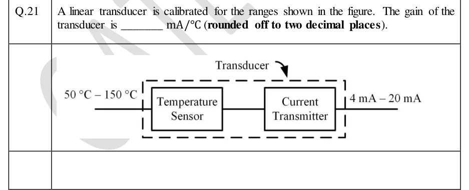
GATE 2024 IN question 21: Block diagram: a dashed box labelled 'Transducer' contains two solid blocks in series, 'Temperature Sensor' followed by…Tap to open full size
Figure from the GATE 2024 IN paper. It is part of the question.
Figure description

Block diagram: a dashed box labelled 'Transducer' contains two solid blocks in series, 'Temperature Sensor' followed by 'Current Transmitter'. The input line entering the dashed box on the left is labelled '50 °C – 150 °C'. The output line leaving the dashed box on the right is labelled '4 mA – 20 mA'.

Answer and solution
GATE 2024 IN Q.21: answer and solution

PRACTICE

5 questions to test yourself

PRACTICE 11 mark · NAT

A pressure transmitter is calibrated for 50 kPa to 250 kPa with a 4-20 mA output (4 mA at 50 kPa, 20 mA at 250 kPa, linear). The loop current is 10 mA. Find the pressure in kPa.

Answer and solution

Answer: (accepted range )

  1. Fraction of span = (10 − 4)/16 = 0.375.

  2. Span = 250 − 50 = 200 kPa.

  3. P = 50 + 0.375 × 200 = 125 kPa.

PRACTICE 22 marks · NAT

A two-wire loop has a 24 V supply. The transmitter needs a minimum of 12 V across its terminals. Two receivers of 250 Ω each are connected in series in the loop. The two-conductor cable has a resistance of 20 Ω per km per conductor. Find the largest cable length, in km, that still lets the loop carry 20 mA.

Answer and solution

Answer: (accepted range )

  1. Voltage available for cable and receivers = 24 − 12 = 12 V.

  2. Maximum total loop resistance = 12 / 0.020 = 600 Ω.

  3. Receivers take 2 × 250 = 500 Ω, leaving 100 Ω for the cable.

  4. Each km of cable has two conductors: 2 × 20 = 40 Ω per km.

  5. Largest length = 100 / 40 = 2.5 km.

PRACTICE 32 marks · NAT

A differential-pressure transmitter with range 0 to 100 mbar gives 4-20 mA with no square-root extractor. Full-scale flow is 50 m³/h at 100 mbar. Find the loop current, in mA, when the flow is 40 m³/h.

Answer and solution

Answer: (accepted range )

  1. Q/Q_max = 40/50 = 0.8.

  2. Differential pressure = 100 × 0.8² = 64 mbar, i.e. 0.64 of span.

  3. I = 4 + 16 × 0.64 = 4 + 10.24 = 14.24 mA.

PRACTICE 42 marks · MSQ

Which of the following statements about a 4-20 mA two-wire transmitter loop are correct?

  1. (A)

    The 4 mA live zero lets a broken wire (0 mA) be told apart from a measurement at 0 % of span.

  2. (B)

    While the supply is large enough for the transmitter to regulate, the loop current does not depend on the cable resistance.

  3. (C)

    The current is larger at the transmitter end of the cable than at the receiver end because of the wire resistance.

  4. (D)

    A HART digital signal is superimposed on the loop with zero mean, so the analog current value is not changed.

Answer and solution

Answer: (A), (B), (D)

  1. A is true: 0 mA cannot be a valid reading when 0 % is 4 mA.

  2. B is true within compliance: a series loop carries one current.

  3. C is false: in a series loop the same current flows through every point.

  4. D is true: the FSK signal has zero average.

PRACTICE 51 mark · MCQ

A receiver on a 4-20 mA loop reads 0 mA. Which is the most likely cause?

  1. (A)

    The measured variable is at the lower range value.

  2. (B)

    The loop is open, or the supply or transmitter has failed.

  3. (C)

    The measured variable is at the upper range value.

  4. (D)

    The receiver resistance is too small.

Answer and solution

Answer: (B)

  1. The lower range value gives 4 mA, not 0 mA.

  2. The upper range value gives 20 mA.

  3. A small receiver resistance still carries the loop current.

  4. A reading of 0 mA is therefore a fault such as a broken wire or a failed supply.

OFFICIAL GATE 2027 SYLLABUS WORDING

Copied from the GATE 2027 syllabus; see all 2027 syllabi.

GATE IN

instrument and sensor networks, 4–20 mA two-wire transmitter

Preparing in Kolkata? IAE Academy's course for GATE IN.