IAE Academy

GATE IN

Motion & force

Displacement, velocity, acceleration, force, torque and vibration

This topic covers the transducers that turn motion and mechanical loading (displacement, velocity, acceleration, force, torque, vibration and shock) into electrical signals. Questions turn on a few results: how an encoder's pulse count sets resolution and speed, how the seismic instrument's frequency ratio decides between accelerometer and vibrometer, how a piezoelectric sensor's circuit sets its low-frequency limit, and how a strain-gauge element converts force or torque into bridge voltage. SI units are used throughout; the gauge factor is .

2 previous-year questions · 2 solved · 5 practice questions

Displacement transducers

A potentiometer converts linear or angular position into a voltage by a sliding contact (wiper) on a resistive track. With supply , track length and wiper position , the unloaded output is , proportional to . The contact wears, adds friction and limits resolution (a wire-wound track moves in steps of one turn of wire).

LOADED POTENTIOMETER

is the total track resistance and the load across the wiper. For the output is , which is linear. A finite load makes it nonlinear. For the error (unloaded minus loaded output, as a fraction of ) is approximately , largest near , where it is about .

The LVDT (linear variable differential transformer) has one primary and two identical secondaries wound in series opposition, with a movable magnetic core. At the centre (null) position the two secondary voltages are equal, so the differential output is ideally zero. In practice a small residual null voltage remains, caused by harmonics in the excitation and stray capacitance. Moving the core one way raises one secondary voltage and lowers the other, and within the linear range the output amplitude is proportional to displacement. Sensitivity is usually quoted in mV per volt of excitation per mm. The output phase reverses by 180° when the core crosses the null, so a phase-sensitive demodulator is needed to recover the direction. There is no contact, so friction is low and resolution is very fine, limited by the noise of the electronics. The angular version is the RVDT (rotary variable differential transformer).

A capacitive transducer changes by changing the plate gap , the overlap area , or the dielectric. Changing gives , which is nonlinear. Changing the overlap area gives , which is linear. In a differential arrangement a moving plate sits between two fixed plates, and a bridge or ratio circuit that measures gives an output linear in displacement.

CAPACITIVE SENSITIVITY AND DIFFERENTIAL CAPACITOR

The first result is for a change of gap: sensitivity rises as the gap shrinks. The second is for a centre plate moved by from the middle of two fixed plates, each at gap when centred, so and .

An optical encoder has a disc with transparent and opaque slots, a light source and photodetectors. An incremental encoder gives pulses, so position comes from counting them, and the count is lost at power-off. It needs a reference (index) pulse. Two channels A and B are 90° out of phase (quadrature), which gives the direction of rotation. An absolute encoder has several tracks, so each position has a unique binary word. The words are often in Gray code, so only one bit changes between adjacent positions and a misread at a boundary is off by at most one step.

ENCODER RESOLUTION

is the number of slots (pulses per revolution per channel). Resolution is the smallest angle that can be distinguished.

Linear and angular velocity

A tachogenerator is a small generator whose output voltage is proportional to shaft speed. A DC tacho gives a DC voltage whose polarity shows the direction. A permanent-magnet AC tacho (an alternator) gives an output whose amplitude and frequency are both proportional to speed. An AC drag-cup tacho is excited at a fixed frequency: its output is at the excitation frequency, its amplitude is proportional to speed, and its phase reverses when the direction reverses. The constant may be given in V per rad/s or in V per 1000 rpm, so check the unit before using it.

TACHOGENERATOR

in rad/s, in V per rad/s, in rpm.

SPEED FROM AN ENCODER OR A TOOTHED WHEEL

For an encoder, is the pulse frequency of one channel and the pulses per revolution of that channel; with decoding, use the count rate and . For a variable-reluctance (magnetic) pickup facing a toothed ferromagnetic wheel, each tooth gives one pulse, so is the number of teeth: .

A moving-coil (electrodynamic) velocity transducer moves a coil of active length through a radial magnetic field , so the emf is proportional to linear velocity . A stroboscope measures speed without contact: a mark on the shaft appears stationary when the flash rate equals the rotational speed or a submultiple of it. If a single stationary image appears at two successive flash rates (flashes per minute), the speed is rpm.

For a rotating wheel or shaft, linear velocity follows from the angular velocity as . Angular acceleration can be found by differentiating a tachogenerator's output (which amplifies noise) or measured directly with a rotational seismic accelerometer: an inertia on a torsional spring of stiffness . For angular frequencies well below its natural frequency , its relative twist is about .

Seismic instrument: accelerometer and vibrometer

A seismic (inertial) transducer has a mass on a spring and damper inside a case fixed to the vibrating body. Let be the case displacement and the displacement of the mass relative to the case. The relative displacement is what is sensed. Then , a second-order system with natural frequency and damping ratio .

RELATIVE DISPLACEMENT FOR BASE MOTION Y = Y SIN ΩT

and are amplitudes. For , and the relative motion is about 180° out of phase with the base motion (vibrometer).

ACCELEROMETER RESPONSE

is proportional to the acceleration amplitude when , with static sensitivity (relative displacement per unit acceleration). For the second factor is .

PHASE LAG OF THE SEISMIC INSTRUMENT

The angle by which the relative displacement lags the input acceleration, taken between 0° and 180° (90° at ). For and , is nearly proportional to frequency, so a waveform with several frequency components is delayed but not distorted.

Use

Frequency range

Design

What the output follows

Accelerometer

(roughly up to 0.2 to 0.4)

High (small mass, stiff spring),

Acceleration ()

Vibrometer (seismometer)

(roughly above 3)

Low (large mass on a soft spring), moderate damping ( to 0.7)

Displacement ()

EXAM TIP

Raising widens the accelerometer's usable frequency range but lowers its sensitivity . This trade-off is the usual reason a question asks which accelerometer to pick. Near with small the response has a sharp resonant peak, so a lightly damped seismic instrument must not be used near its natural frequency.

Piezoelectric accelerometers, vibration and shock

A piezoelectric accelerometer loads a quartz or ceramic crystal with a small seismic mass. Below resonance the crystal force is , so the generated charge is proportional to acceleration. It is a self-generating, very stiff sensor, so its natural frequency is high (typically tens of kHz). It therefore covers a wide frequency range upward and suits shock and high-frequency vibration. It cannot measure steady (DC) acceleration, because the charge leaks away through the finite insulation and amplifier input resistance.

PIEZOELECTRIC CHARGE AND OPEN-CIRCUIT VOLTAGE

is the charge sensitivity in C/N. is the crystal capacitance, the cable capacitance and the amplifier input capacitance. Cable length changes the voltage sensitivity, so a charge amplifier () is used to remove that dependence.

VOLTAGE SENSITIVITY OF A CRYSTAL

is the voltage coefficient in V m/N, the crystal thickness and the applied stress. This is the open-circuit voltage of the crystal alone, with .

LOW-FREQUENCY CUT-OFF OF A PIEZOELECTRIC SENSOR CIRCUIT

For a voltage amplifier, is the combined leakage and input resistance and the total capacitance of sensor, cable and amplifier input. With a charge amplifier, the feedback resistor and capacitor set the −3 dB point.

SINUSOIDAL VIBRATION AMPLITUDES

is the displacement amplitude and the vibration frequency in Hz.

A shock is a short, non-repeating, high-amplitude transient. It contains a wide range of frequencies, so the accelerometer needs a natural frequency well above the highest significant frequency in the pulse. It also needs a low enough low-frequency cut-off: the circuit time constant must be much longer than the pulse duration, or the recorded pulse droops and undershoots. A vibration is a continuing oscillation, and the instrument and its range are chosen from its frequency and amplitude.

Force and torque measurement

Force is measured by letting it deform an elastic member and sensing the deformation. In a strain-gauge load cell the member (a column, beam or ring) has strain gauges bonded to it. A proving ring is a steel ring whose diametral deflection is proportional to the applied force, and the deflection is read by a dial gauge or a displacement sensor such as an LVDT.

GAUGE FACTOR

is Poisson's ratio of the gauge material and the fractional change in its resistivity (the piezoresistive effect). For metal-foil gauges ; semiconductor gauges have a much larger, temperature-sensitive .

COLUMN LOAD CELL

Axial load on cross-section of Young's modulus , within the elastic limit. A gauge bonded across the column sees the transverse strain .

STRAIN-GAUGE BRIDGE OUTPUT

Equal arms, bridge balanced at zero strain, signs of the active arms arranged so their effects add. The half- and full-bridge results with equal and opposite strains are exactly linear. Temperature effects cancel when identical gauges at the same temperature sit in adjacent arms (a dummy gauge does this for one active gauge).

For torque, gauges are bonded on the shaft surface at to the axis, which are the directions of the principal strains in pure torsion. These have equal size and opposite sign, , where is the surface shear stress and the shear modulus of the shaft. Four gauges, two pairs at on diametrically opposite sides of the shaft, wired as a full bridge so that the torsion strains add, give the largest output and reject axial load, bending and uniform temperature change. On a rotating shaft the signal is taken off by slip rings or telemetry. A magnetostrictive torque sensor, which detects the change in a ferromagnetic shaft's permeability under stress, needs no contact.

SOLID CIRCULAR SHAFT UNDER TORQUE T

is the shaft diameter in metres, in N m, in Pa. Mechanical power transmitted is .

EXAM TIP

Do not confuse the shear modulus with the gauge factor . Both are written in many texts. Write units: in mm used directly makes too large by , so the strain comes out times too small.

Worked examples

WORKED EXAMPLE · ACCELEROMETER ERROR

A seismic accelerometer has natural frequency 500 Hz and damping ratio . It measures a sinusoidal acceleration at 100 Hz. Find the amplitude ratio relative to the ideal low-frequency value (taken as 1) and the percentage error.

Solution
  1. .

  2. For the factor is .

  3. , so the factor is .

  4. Error .

Answer: Amplitude ratio about 0.9992, an error of about 0.08% (the reading is slightly low).

WORKED EXAMPLE · TORQUE ON A SHAFT

A solid steel shaft of diameter 40 mm (shear modulus 80 GPa) transmits a torque of 500 N m. Four gauges (gauge factor 2) at form a full bridge with all four arms active, supplied with 10 V. Find the bridge output.

Solution
  1. .

  2. .

  3. Full bridge: .

  4. V.

Answer: About 4.97 mV.

PREVIOUS-YEAR QUESTIONS

2 questions from the IN papers

Try each question first, then open the answer. We placed each question under a topic ourselves; the exam paper does not label topics.

See these papers in full: GATE IN 2025 · GATE IN 2020

GATE 2025 IN Q.14

GATE 2025 · INQ.14 · 1 mark · MCQ

The primary coil of a linear variable differential transformer (LVDT) is supplied with AC voltage as shown in the figure. The secondary coils are connected in series opposition and the output is measured using a true RMS voltmeter. The displacement x of the core is indicated in mm on a linear scale. At the null position x = 0, the voltmeter reads 0 V. If the voltmeter reads 0.2 V for a displacement of x = +2 mm, then for a displacement of x = -3 mm, the voltmeter reading, in V, is
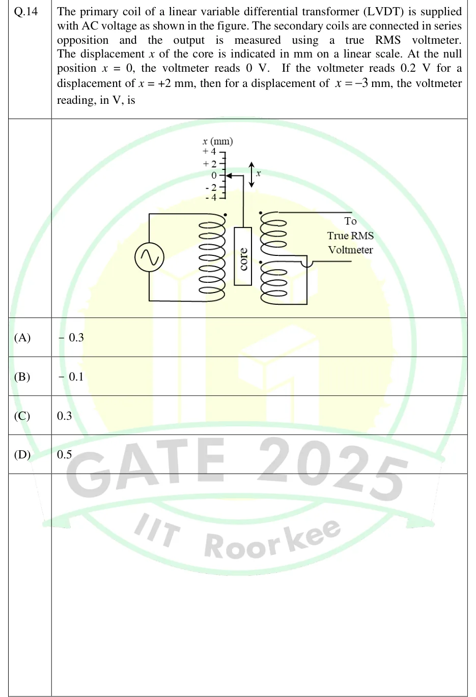
GATE 2025 IN question 14: An AC source drives the primary coil of an LVDT (primary on the left, dotted top terminal).Tap to open full size
Figure from the GATE 2025 IN paper. It is part of the question.
Figure description

An AC source drives the primary coil of an LVDT (primary on the left, dotted top terminal). A movable cylindrical core, marked 'core', sits between the primary and the two secondary windings, attached by a rod to a pointer on a linear scale labelled x (mm) with marks +4, +2, 0, -2, -4. A double-headed arrow beside the rod shows the core moves up and down (x). The two dotted secondary coils are wired in series opposition, with their free ends going 'To True RMS Voltmeter'.

  1. (A)

    -0.3

  2. (B)

    -0.1

  3. (C)

    0.3

  4. (D)

    0.5

Answer and solution
GATE 2025 IN Q.14: answer and solution

GATE 2020 IN Q.53

GATE 2020 · INQ.53 · 2 marks · NAT

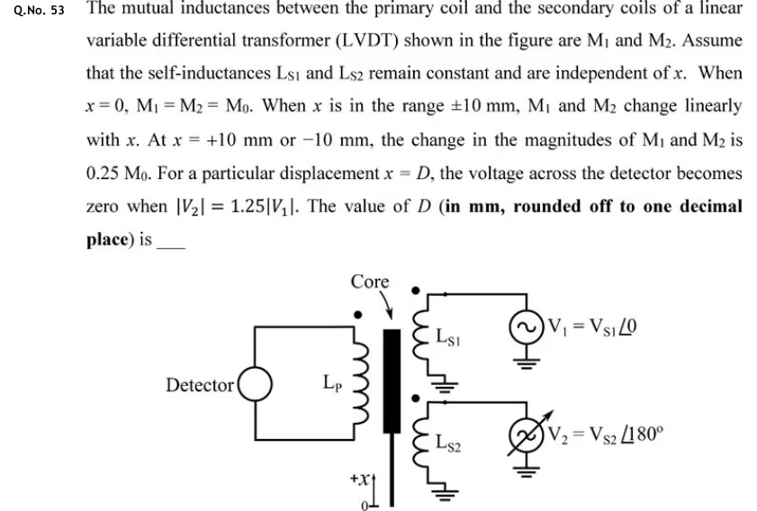
The mutual inductances between the primary coil and the secondary coils of a linear variable differential transformer (LVDT) shown in the figure are M1 and M2. Assume that the self-inductances Ls1 and Ls2 remain constant and are independent of x. When x = 0, M1 = M2 = M0. When x is in the range ±10 mm, M1 and M2 change linearly with x. At x = +10 mm or −10 mm, the change in the magnitudes of M1 and M2 is 0.25 M0. For a particular displacement x = D, the voltage across the detector becomes zero when |V2| = 1.25|V1|. The value of D (in mm, rounded off to one decimal place) is ___

GATE 2020 IN question 53: LVDT schematic.Tap to open full size
Figure from the GATE 2020 IN paper. It is part of the question.
Figure description

LVDT schematic. A vertical core (black bar, labelled Core) sits between a primary coil Lp on the left and two secondary coils Ls1 (upper) and Ls2 (lower) on the right, each with a dot marking. The primary is connected in a closed loop to a Detector (circle) on the far left. Ls1 is driven by source V1 = Vs1 at angle 0, and Ls2 by source V2 = Vs2 at angle 180 degrees (an adjustable source), both returned to ground. Displacement axis +x points upward from the zero (0) mark at the bottom.

Answer and solution
GATE 2020 IN Q.53: answer and solution

PRACTICE

5 questions to test yourself

PRACTICE 11 mark · MCQ

An incremental optical encoder has 1024 slots per revolution on each channel (channels A and B in quadrature). The counter uses decoding. What is the smallest angle it can resolve?

  1. (A)

    0.352°

  2. (B)

    0.0879°

  3. (C)

    0.176°

  4. (D)

    0.0439°

Answer and solution

Answer: (B)

  1. With decoding, counts per revolution .

  2. Resolution .

PRACTICE 21 mark · NAT

An incremental encoder gives 600 pulses per revolution on channel A. The pulse frequency measured on channel A alone is 5 kHz. Find the shaft speed in rpm.

Answer and solution

Answer: (accepted range )

  1. .

  2. rpm.

PRACTICE 32 marks · NAT

A seismic accelerometer has natural frequency 400 Hz and damping ratio 0.707. It measures a sinusoidal acceleration of frequency 160 Hz. Taking the low-frequency response as the ideal value, find the amplitude error as a percentage, , using the exact second-order response.

Answer and solution

Answer: (accepted range )

  1. .

  2. Ratio .

  3. Ratio (with taken as exactly , ).

  4. Error .

PRACTICE 42 marks · MSQ

Which of the following statements about seismic vibration transducers are correct?

  1. (A)

    For frequency ratio much greater than 1, the relative displacement amplitude tends to the displacement amplitude of the vibrating body.

  2. (B)

    For use as an accelerometer, the vibration frequency should be well below the natural frequency of the instrument.

  3. (C)

    At low frequency, the relative displacement per unit acceleration of a seismic accelerometer is , so raising its natural frequency lowers its sensitivity.

  4. (D)

    An undamped seismic accelerometer has a flat response up to the frequency ratio .

Answer and solution

Answer: (A), (B), (C)

  1. A is true: for (vibrometer).

  2. B is true: the acceleration response is flat only for .

  3. C is true: as .

  4. D is false: with no damping the factor rises steadily and grows without limit at (resonance).

PRACTICE 52 marks · NAT

A short steel column of cross-sectional area 400 mm and Young's modulus 200 GPa carries an axial load of 40 kN. One strain gauge of gauge factor 2.0 is bonded axially as the only active arm of a Wheatstone bridge supplied with 5 V. Ignore Poisson effects and use the small-signal approximation . Find the output in mV.

Answer and solution

Answer: (accepted range )

  1. .

  2. .

  3. V.

  4. mV.

OFFICIAL GATE 2027 SYLLABUS WORDING

Copied from the GATE 2027 syllabus; see all 2027 syllabi.

GATE IN

transducers for industrial instrumentation: displacement, velocity, acceleration (linear and angular), force, torque, vibration, shock

Preparing in Kolkata? IAE Academy's course for GATE IN.