
IAE Academy

GATE 2025 IN Q.14: solution and answer

GATE 2025 · INQ.14 · 1 mark · MCQ

The primary coil of a linear variable differential transformer (LVDT) is supplied with AC voltage as shown in the figure. The secondary coils are connected in series opposition and the output is measured using a true RMS voltmeter. The displacement x of the core is indicated in mm on a linear scale. At the null position x = 0, the voltmeter reads 0 V. If the voltmeter reads 0.2 V for a displacement of x = +2 mm, then for a displacement of x = -3 mm, the voltmeter reading, in V, is
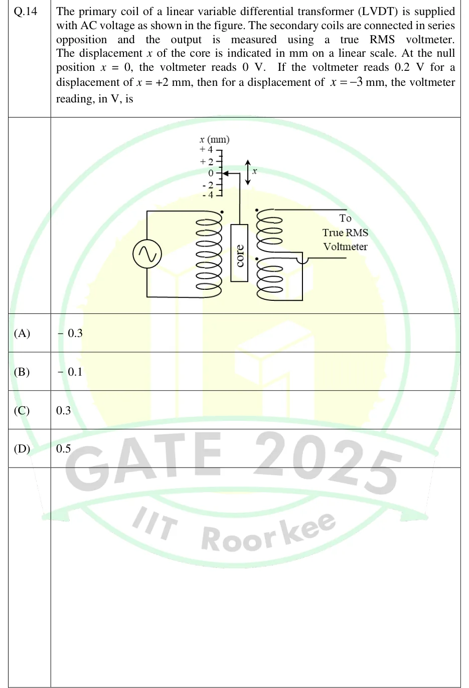
GATE 2025 IN question 14: An AC source drives the primary coil of an LVDT (primary on the left, dotted top terminal).Tap to open full size
Figure from the GATE 2025 IN paper. It is part of the question.
Figure description

An AC source drives the primary coil of an LVDT (primary on the left, dotted top terminal). A movable cylindrical core, marked 'core', sits between the primary and the two secondary windings, attached by a rod to a pointer on a linear scale labelled x (mm) with marks +4, +2, 0, -2, -4. A double-headed arrow beside the rod shows the core moves up and down (x). The two dotted secondary coils are wired in series opposition, with their free ends going 'To True RMS Voltmeter'.

  1. (A)

    -0.3

  2. (B)

    -0.1

  3. (C)

    0.3

  4. (D)

    0.5

Answer and solution

ANSWER

The voltmeter reads 0.3 V, which is option (C).

Official answer: CSource: Official answer key, GATE 2025 IN (IIT Roorkee)

  1. The secondary coils are in series opposition, so the net output is . At null () the two induced voltages are equal and V.

  2. Within the linear range the output amplitude is proportional to the core displacement from null: .

  3. From the given reading, .

  4. For the amplitude is .

  5. Moving the core to the other side of null reverses the phase of the output by . The sign of the displacement is carried only by this phase.

  6. A true RMS voltmeter reads the RMS value of the waveform. This value is never negative and does not show the phase. So it reads , not , and option (C) is correct.

KEY IDEA

An LVDT output amplitude is proportional to the core's distance from null. The side of null shows up only as a 180 degree phase change. A true RMS voltmeter cannot show phase, so it reads the magnitude, which is always positive.

WATCH OUT FOR

Treating the output as a signed DC-like quantity and picking -0.3 V for a negative displacement. Another slip is using only the magnitude scaling and choosing -0.1 V or 0.5 V by adding or subtracting readings.

From the GATE 2025 IN paper. Every question of this paper · Download the full paper · All 2 Motion & force questions, with notes