
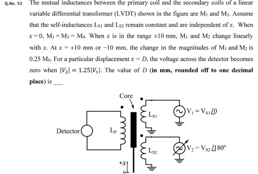
The mutual inductances between the primary coil and the secondary coils of a linear variable differential transformer (LVDT) shown in the figure are M1 and M2. Assume that the self-inductances Ls1 and Ls2 remain constant and are independent of x. When x = 0, M1 = M2 = M0. When x is in the range ±10 mm, M1 and M2 change linearly with x. At x = +10 mm or −10 mm, the change in the magnitudes of M1 and M2 is 0.25 M0. For a particular displacement x = D, the voltage across the detector becomes zero when |V2| = 1.25|V1|. The value of D (in mm, rounded off to one decimal place) is ___
 Tap to open full size
Figure description
LVDT schematic. A vertical core (black bar, labelled Core) sits between a primary coil Lp on the left and two secondary coils Ls1 (upper) and Ls2 (lower) on the right, each with a dot marking. The primary is connected in a closed loop to a Detector (circle) on the far left. Ls1 is driven by source V1 = Vs1 at angle 0, and Ls2 by source V2 = Vs2 at angle 180 degrees (an adjustable source), both returned to ground. Displacement axis +x points upward from the zero (0) mark at the bottom.