
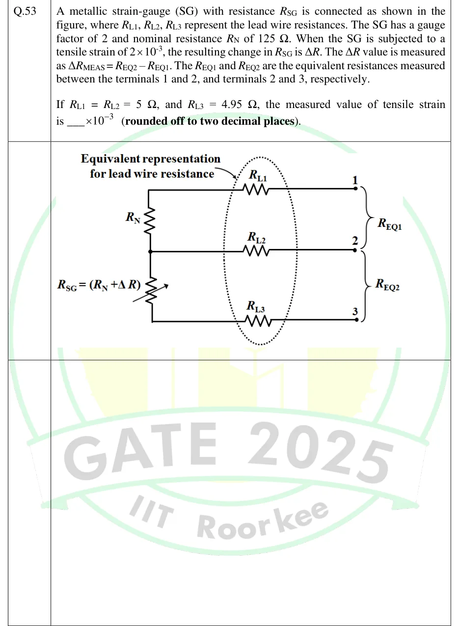
A metallic strain-gauge (SG) with resistance is connected as shown in the figure, where , , represent the lead wire resistances. The SG has a gauge factor of 2 and nominal resistance of 125 . When the SG is subjected to a tensile strain of , the resulting change in is . The value is measured as . The and are the equivalent resistances measured between the terminals 1 and 2, and terminals 2 and 3, respectively. If and , the measured value of tensile strain is ___ (rounded off to two decimal places).
 Tap to open full size
Figure description
Three-wire strain gauge connection. Fixed resistor R_N sits above the strain gauge R_SG = (R_N + ΔR), drawn as a variable resistor, in series on the left. The top end of R_N goes through lead resistance R_L1 to terminal 1. The junction between R_N and R_SG goes through R_L2 to terminal 2. The bottom end of R_SG goes through R_L3 to terminal 3. A dotted ellipse around R_L1, R_L2 and R_L3 is labelled 'Equivalent representation for lead wire resistance'. Brace R_EQ1 spans terminals 1 and 2, and brace R_EQ2 spans terminals 2 and 3.