
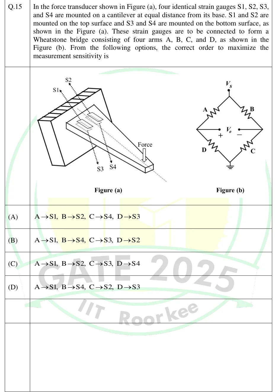
In the force transducer shown in Figure (a), four identical strain gauges S1, S2, S3, and S4 are mounted on a cantilever at equal distance from its base. S1 and S2 are mounted on the top surface and S3 and S4 are mounted on the bottom surface, as shown in the Figure (a). These strain gauges are to be connected to form a Wheatstone bridge consisting of four arms A, B, C, and D, as shown in the Figure (b). From the following options, the correct order to maximize the measurement sensitivity is
 Tap to open full size
Figure description
Figure (a): a cantilever beam fixed to a wall at the left, extending to the right with a downward Force arrow at the free end. S1 and S2 are two strain gauges on the top surface near the fixed end, side by side, and S3 and S4 are on the bottom surface at the same positions (dotted lines run through to the underside). Figure (b): a Wheatstone bridge with excitation Vs at the top node and ground at the bottom node. Arm A is top-left, B is top-right, C is bottom-right and D is bottom-left. The output Vo is taken between the left node (A-D junction, marked +) and the right node (B-C junction, marked -).
- (A)
A→S1, B→S2, C→S4, D→S3
- (B)
A→S1, B→S4, C→S3, D→S2
- (C)
A→S1, B→S2, C→S3, D→S4
- (D)
A→S1, B→S4, C→S2, D→S3