IAE Academy

GATE EE

Per-unit system, bus admittance matrix and load flow

The per-unit system rescales every voltage, current, power and impedance to chosen bases, so a network with several voltage levels can be solved as one. The bus admittance matrix and the load-flow methods (Gauss-Seidel, Newton-Raphson, fast decoupled and DC) are the standard way to find bus voltages from specified powers. Typical questions ask for base conversions, Ybus entries, one Gauss-Seidel step, Jacobian sizes and the statements that distinguish the methods.

10 previous-year questions · 10 solved · 6 practice questions

Per-unit quantities and choosing bases

A per-unit value is the actual value divided by a base value of the same unit: . Only two bases are chosen freely, usually the three-phase MVA base and the line-to-line kV base. The current and impedance bases then follow from them.

Convention used throughout: is the three-phase MVA, is the line-to-line voltage in kV, and the impedance is the per-phase value of the equivalent star circuit. is the imaginary unit and phasors are written as magnitudeangle.

BASE CURRENT AND BASE IMPEDANCE

Three-phase MVA base in MVA and line-to-line kV base in kV; the impedance is per phase of the equivalent star.

PER-UNIT IMPEDANCE

Per-unit voltage, current and power follow in the same way: , , .

CHANGE OF BASE

Used when an equipment rating (given on its own MVA and kV) must be moved to the system base; the rated MVA and kV are the old base.

Equipment reactances are normally quoted in per unit on the equipment's own rating. Before they can be combined, every one must be converted to the common system base using the change-of-base formula.

WORKED EXAMPLE

A generator rated 50 MVA, 11 kV has a reactance of 0.2 pu on its own rating. Express it on a base of 100 MVA, 10.5 kV.

Solution
  1. Old base: 50 MVA, 11 kV. New base: 100 MVA, 10.5 kV.

  2. .

  3. , so .

Answer: pu

EXAM TIP

The voltage ratio in the change-of-base formula is squared and goes old over new. The MVA ratio goes new over old. If only the MVA base changes, the voltage factor is 1.

Per-unit across transformers

A system with transformers has several voltage levels. Choose one for the whole system. Choose the of each section so that the base voltages on the two sides of a transformer are in the ratio of its rated (line-to-line) voltages.

With this choice, the ideal transformer disappears from the per-unit network: the per-unit voltage and per-unit impedance are the same whichever side they are referred to. The transformer is then represented only by its per-unit leakage impedance, converted to the system base.

  1. Pick for the system and for one section.

  2. Obtain the other sections' by multiplying by the transformer rated-voltage ratios.

  3. Convert every equipment per-unit value to the new bases with the change-of-base formula.

  4. Convert load powers and voltages to per unit on the same bases.

  5. Solve the per-unit network, then multiply by the bases to get actual values.

BASE VOLTAGE ACROSS A TRANSFORMER

Line-to-line rated voltages of the transformer; is unchanged across it.

Advantage of per unit

Reason

Transformers need no turns-ratio in the network

Bases follow the rated-voltage ratio, so the ideal transformer has ratio 1:1

Values lie in a narrow range

Voltages are near 1 pu, which makes errors easy to spot

Same impedance referred to either side

Per-unit leakage impedance does not depend on the side

Three-phase relations take the single-phase form

With a three-phase MVA base and a line-to-line kV base, ; the factors of and 3 cancel

EXAM TIP

If a transformer's tap setting is off-nominal, the base voltages still follow the rated ratio, and the off-nominal tap appears as a ratio in the per-unit model. Its Ybus entries are given in the next section.

Bus types and the power-flow equations

At each bus there are four quantities: , , and . Two are specified and two are found, and the choice decides the bus type. and here are net injections: generation minus load, and .

Bus type

Specified

To be found

Typical use

Slack (swing)

,

,

One generator bus; supplies the losses, which are not known in advance

PV (voltage-controlled)

,

,

Generator buses with voltage control

PQ (load)

,

,

Load buses, and buses with no generation or load ()

For a system of buses with one slack bus and PV buses, there are PQ buses. The unknowns are angles and voltage magnitudes, which is in all. The same number of equations is available: at every non-slack bus and at every PQ bus.

A PV bus can hold its voltage only while its generator's reactive power stays within limits. If the computed goes outside , is fixed at the violated limit and the bus is treated as a PQ bus, so its voltage magnitude becomes an unknown.

COMPLEX POWER INJECTED AT BUS $I$

Phasors in per unit; are elements of the bus admittance matrix.

REAL AND REACTIVE POWER EQUATIONS

Here and . The equations are non-linear, so they are solved by iteration.

LINE FLOW AND LINE LOSS

is the complex power leaving bus towards bus ; is the series admittance and is half the line charging (the pi-model shunt at bus ). Once the voltages are known, these give line flows, line losses and the slack-bus power.

Bus admittance matrix

The bus admittance matrix relates the bus current injections to the bus voltages: . The reference (ground) is not a bus and has no row or column. For a network with no mutual coupling between elements and no off-nominal transformers, it can be written down by inspection.

  1. Diagonal element : the sum of all admittances connected to bus , including shunt admittances (line charging, capacitors, reactors) at that bus.

  2. Off-diagonal element : the negative of the admittance of the element connected directly between buses and ; zero if there is none.

  3. Use admittances of the series elements, and half the total line charging at each end of a pi-model line.

ELEMENTS OF THE BUS ADMITTANCE MATRIX

is the total shunt admittance from bus to ground; is the series admittance between and . Valid with no mutual coupling and nominal-ratio transformers.

YBUS FROM THE INCIDENCE MATRIX

is the element-bus incidence matrix (one row per element, one column per bus, reference column removed) and is the primitive admittance matrix of the elements (diagonal when there is no mutual coupling).

OFF-NOMINAL TAP TRANSFORMER BETWEEN BUSES $I$ AND $K$

Ideal transformer of ratio on the bus- side, in series with leakage admittance (per unit) on the bus- side. For a real tap , and the matrix stays symmetric; a phase shifter (complex ) makes .

Property

Statement

Symmetry

when there are no phase shifters; it is complex symmetric, not Hermitian

Sparsity

Most elements are zero, since a bus connects to few others

Row sums

For lines and nominal-ratio transformers, each row sums to the shunt admittance at that bus; with no shunts at all, every row sums to zero and is singular

Adding a line between and

Adds (plus half the line charging) to and , and subtracts from and

Adding a shunt at bus

Changes only

Removing a line

The opposite change to adding it

NUMBER OF NON-ZERO ELEMENTS AND SPARSITY

buses; is the number of distinct bus pairs joined directly by at least one element (parallel lines count once, shunts to ground do not count). Sparsity is the fraction of elements that are zero.

EXAM TIP

Do not confuse with . is sparse and built by inspection; is its inverse and is generally full.

Gauss-Seidel load flow

Gauss-Seidel solves the equations bus by bus. The voltage of bus is recomputed from the latest available voltages of all other buses. The slack bus is never updated. Below, is the iteration number and is a bus index.

GAUSS-SEIDEL UPDATE (PQ BUS)

and are net injections in per unit. Buses already updated in this iteration use their new values.

ACCELERATION FACTOR

Here is typically between 1 and 2 (about 1.6), which speeds up convergence; gives plain Gauss-Seidel.

At a PV bus the reactive power is not known, so it is first computed from the present voltages. If it lies within the generator's limits, it is used in the update, and the magnitude of the new voltage is then reset to the specified value, keeping only its angle. If it violates a limit, is set to that limit and the bus is updated as a PQ bus.

REACTIVE POWER AT A PV BUS

Use the latest available values of ; then set after the update, keeping the angle.

WORKED EXAMPLE

Two buses are joined by a line of impedance pu. Bus 1 is the slack with . Bus 2 is a load bus drawing pu, with initial guess . Find by one Gauss-Seidel step.

Solution
  1. , so and .

  2. Net injection at bus 2: , , so .

  3. .

  4. Since : .

Answer: pu, magnitude about pu

EXAM TIP

A load is a negative injection. Writing with and as net injections is where most sign errors occur.

Newton-Raphson, fast decoupled and DC load flow

Newton-Raphson linearises the power equations about the present estimate. At each iteration the mismatches and are computed, the Jacobian is formed, and the corrections to angle and magnitude are found from a linear system.

NEWTON-RAPHSON CORRECTION EQUATION

Mismatch , ; update , and repeat.

SIZE OF THE JACOBIAN

buses, one slack, PV buses (polar form). is , is , is and is .

Fast decoupled load flow exploits the strong coupling of with and of with in transmission networks. It neglects and and replaces and by constant matrices, which are formed and factorised once. The approximations are , and .

FAST DECOUPLED EQUATIONS

is , built from series reactances only: diagonal , off-diagonal (shunts and resistances ignored). is : the negative of the imaginary part of , for the PQ rows and columns. Both are constant.

DC LOAD FLOW

Assumes pu at all buses, , small angle differences, so . Angles in radians. is the same matrix as in the fast decoupled method (from , slack row and column removed), and holds the net real-power injections of the non-slack buses. It gives real power flows only, and no losses.

Feature

Gauss-Seidel

Newton-Raphson

Fast decoupled

Convergence

Linear, slow

Quadratic, fast

Linear, but faster than Gauss-Seidel

Iterations needed

Many

Few

More than Newton-Raphson

Effect of system size on iterations

Iterations grow with the number of buses

Nearly independent of system size

Nearly independent of system size

Work per iteration

Small

Large (Jacobian built and solved)

Small (constant matrices)

Memory

Small

Large

Moderate

Matrices

Uses directly

Jacobian changes each iteration

and constant

EXAM TIP

The Jacobian size is , not . Each PV bus removes one equation (a row of and ) and one unknown (a column of and ).

PREVIOUS-YEAR QUESTIONS

10 questions from the EE papers

Try each question first, then open the answer. We placed each question under a topic ourselves; the exam paper does not label topics.

See these papers in full: GATE EE 2026 · GATE EE 2025 · GATE EE 2024 · GATE EE 2023 · GATE EE 2020 · GATE EE 2018

GATE 2026 EE Q.18

GATE 2026 · EEQ.18 · 1 mark · MCQ

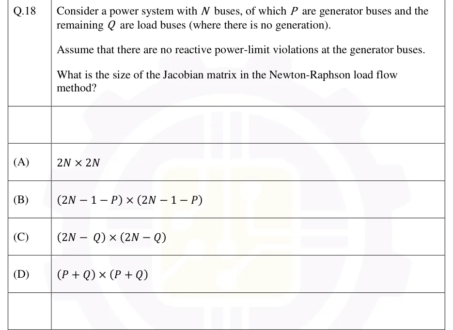
Consider a power system with buses, of which are generator buses and the remaining are load buses (where there is no generation). Assume that there are no reactive power-limit violations at the generator buses. What is the size of the Jacobian matrix in the Newton-Raphson load flow method?

  1. (A)

  2. (B)

  3. (C)

  4. (D)

Answer and solution
See the question in the paper
GATE 2026 EE Q.18: answer and solution

GATE 2026 EE Q.41

GATE 2026 · EEQ.41 · 2 marks · MCQ

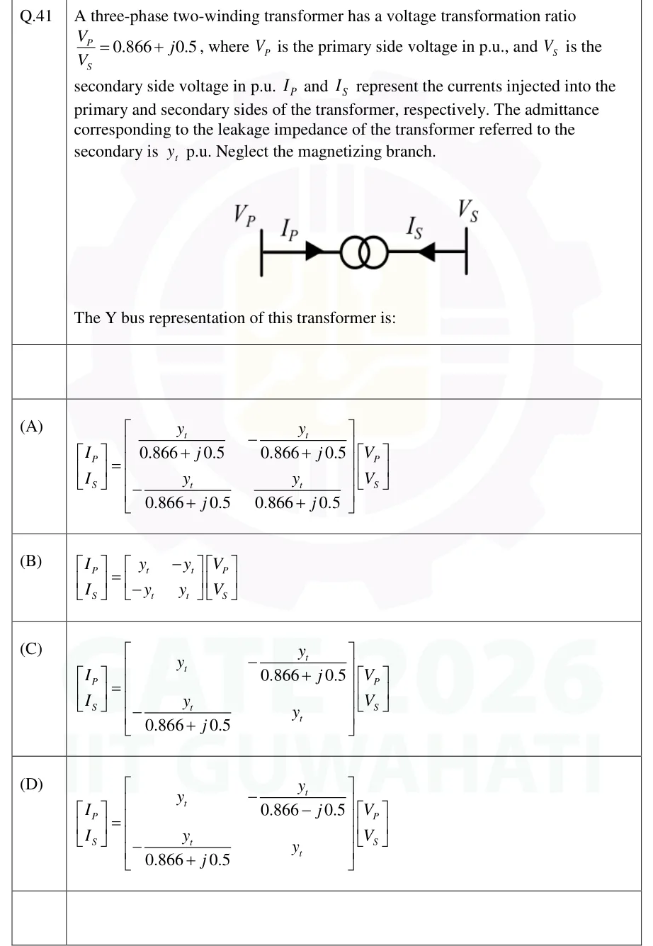
A three-phase two-winding transformer has a voltage transformation ratio , where is the primary side voltage in p.u., and is the secondary side voltage in p.u. and represent the currents injected into the primary and secondary sides of the transformer, respectively. The admittance corresponding to the leakage impedance of the transformer referred to the secondary is p.u. Neglect the magnetizing branch. The Y bus representation of this transformer is:

GATE 2026 EE question 41: Single-line diagram of a transformer symbol (two coupled circles) between two bus bars.Tap to open full size
Figure from the GATE 2026 EE paper. It is part of the question.
Figure description

Single-line diagram of a transformer symbol (two coupled circles) between two bus bars. Left bus carries voltage V_P with current I_P drawn by an arrow pointing into the transformer; right bus carries voltage V_S with current I_S drawn by an arrow pointing into the transformer from the right.

  1. (A)

    Figure — [I_P; I_S] = [[ y_t/(0.866+j0.5), -y_t/(0.866+j0.5) ], [ -y_t/(0.866+j0.5), y_t/(0.866+j0.5) ]] [V_P; V_S]

  2. (B)

    Figure — [I_P; I_S] = [[ y_t, -y_t ], [ -y_t, y_t ]] [V_P; V_S]

  3. (C)

    Figure — [I_P; I_S] = [[ y_t, -y_t/(0.866+j0.5) ], [ -y_t/(0.866+j0.5), y_t ]] [V_P; V_S]

  4. (D)

    Figure — [I_P; I_S] = [[ y_t, -y_t/(0.866-j0.5) ], [ -y_t/(0.866+j0.5), y_t ]] [V_P; V_S]

Answer and solution
GATE 2026 EE Q.41: answer and solution

GATE 2024 EE Q.41

GATE 2024 · EEQ.41 · 2 marks · MCQ

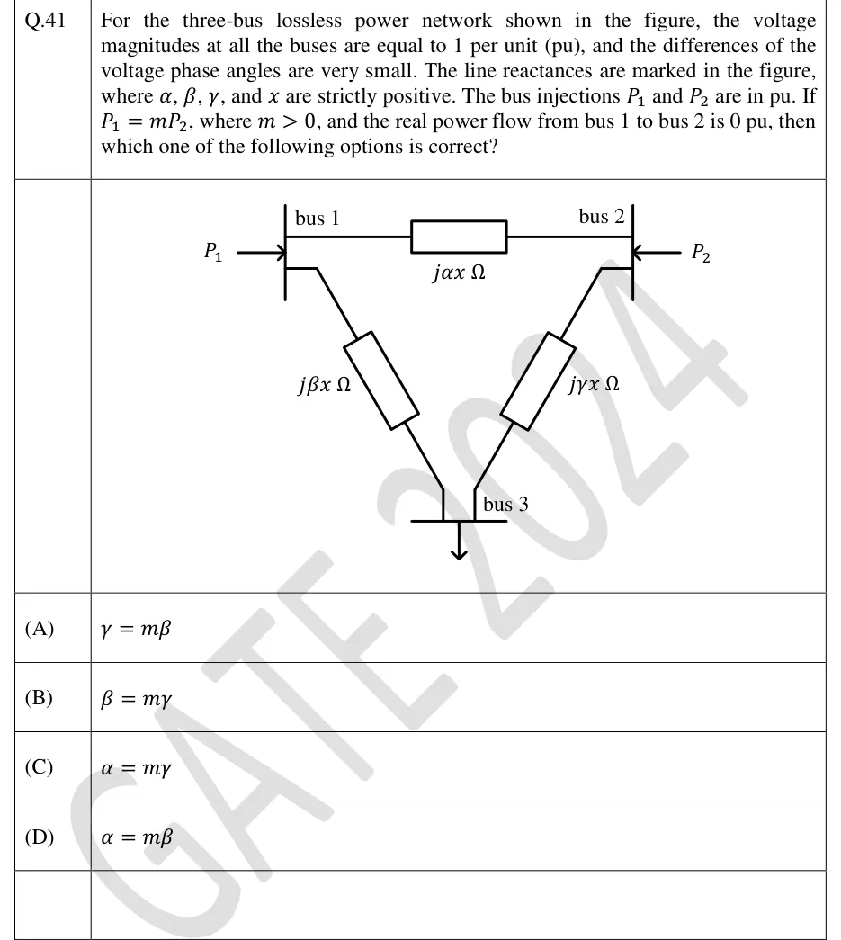
For the three-bus lossless power network shown in the figure, the voltage magnitudes at all the buses are equal to 1 per unit (pu), and the differences of the voltage phase angles are very small. The line reactances are marked in the figure, where , and are strictly positive. The bus injections and are in pu. If , where , and the real power flow from bus 1 to bus 2 is 0 pu, then which one of the following options is correct?

GATE 2024 EE question 41: Triangle network of three buses.Tap to open full size
Figure from the GATE 2024 EE paper. It is part of the question.
Figure description

Triangle network of three buses. Bus 1 (top left) has injection P1 flowing into it; bus 2 (top right) has injection P2 flowing into it. A line between bus 1 and bus 2 carries reactance j alpha x ohm. A line from bus 1 to bus 3 (bottom, drawn with a ground-style arrow) carries reactance j beta x ohm. A line from bus 2 to bus 3 carries reactance j gamma x ohm.

  1. (A)

  2. (B)

  3. (C)

  4. (D)

Answer and solution
GATE 2024 EE Q.41: answer and solution

GATE 2023 EE Q.28

GATE 2023 · EEQ.28 · 1 mark · MSQ

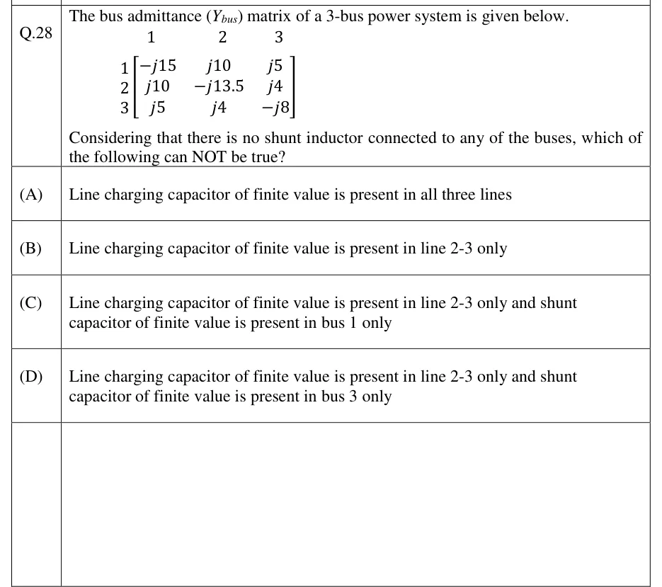
The bus admittance () matrix of a 3-bus power system is given below (rows and columns ordered 1, 2, 3):

Considering that there is no shunt inductor connected to any of the buses, which of the following can NOT be true?

  1. (A)

    Line charging capacitor of finite value is present in all three lines

  2. (B)

    Line charging capacitor of finite value is present in line 2-3 only

  3. (C)

    Line charging capacitor of finite value is present in line 2-3 only and shunt capacitor of finite value is present in bus 1 only

  4. (D)

    Line charging capacitor of finite value is present in line 2-3 only and shunt capacitor of finite value is present in bus 3 only

Answer and solution
See the question in the paper
GATE 2023 EE Q.28: answer and solution

GATE 2023 EE Q.41

GATE 2023 · EEQ.41 · 2 marks · MCQ

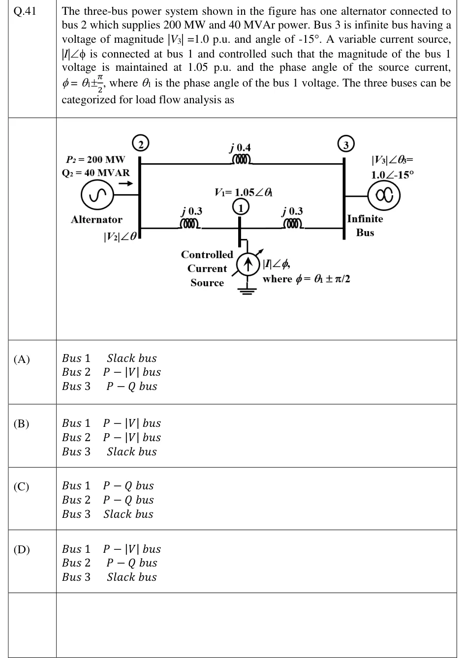
The three-bus power system shown in the figure has one alternator connected to bus 2 which supplies 200 MW and 40 MVAr power. Bus 3 is infinite bus having a voltage of magnitude |V3| = 1.0 p.u. and angle of -15°. A variable current source, |I|∠φ is connected at bus 1 and controlled such that the magnitude of the bus 1 voltage is maintained at 1.05 p.u. and the phase angle of the source current, φ = θ1 ± π/2, where θ1 is the phase angle of the bus 1 voltage. The three buses can be categorized for load flow analysis as

GATE 2023 EE question 41: Single-line diagram of a three-bus system.Tap to open full size
Figure from the GATE 2023 EE paper. It is part of the question.
Figure description

Single-line diagram of a three-bus system. Bus 2 (left vertical bar) has an alternator with P2 = 200 MW, Q2 = 40 MVAR and voltage |V2|∠θ. Bus 3 (right vertical bar) is an infinite bus with |V3|∠θ3 = 1.0∠-15°. Bus 2 and bus 3 are joined by a direct line of reactance j0.4. Bus 1 sits at the midpoint of a lower path: j0.3 from bus 2 to bus 1 and j0.3 from bus 1 to bus 3. At bus 1 the voltage is V1 = 1.05∠θ1, and a controlled current source |I|∠φ, with φ = θ1 ± π/2, is connected from bus 1 to ground.

  1. (A)

    Bus 1: Slack bus; Bus 2: P-|V| bus; Bus 3: P-Q bus

  2. (B)

    Bus 1: P-|V| bus; Bus 2: P-|V| bus; Bus 3: Slack bus

  3. (C)

    Bus 1: P-Q bus; Bus 2: P-Q bus; Bus 3: Slack bus

  4. (D)

    Bus 1: P-|V| bus; Bus 2: P-Q bus; Bus 3: Slack bus

Answer and solution
GATE 2023 EE Q.41: answer and solution

GATE 2020 EE Q.29

GATE 2020 · EEQ.29 · 2 marks · MCQ

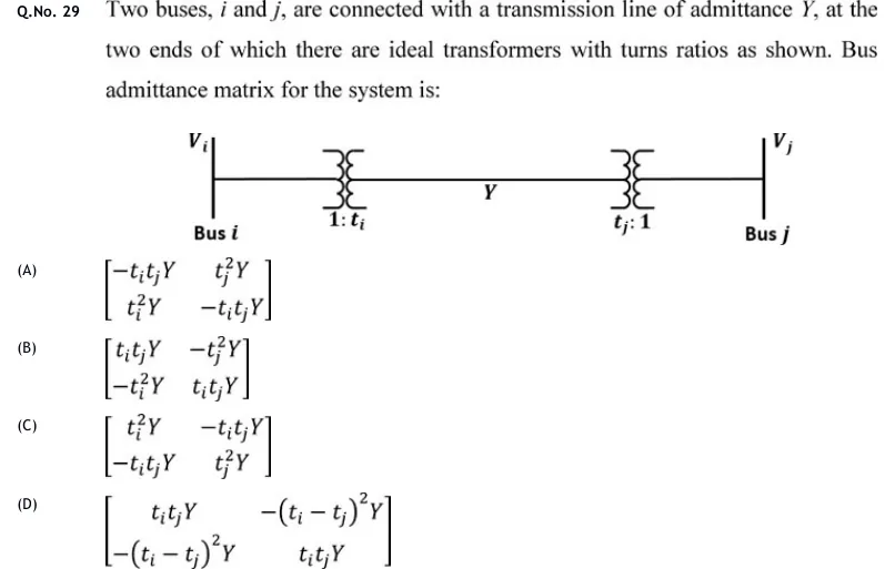
Two buses, and , are connected with a transmission line of admittance , at the two ends of which there are ideal transformers with turns ratios as shown. Bus admittance matrix for the system is:

GATE 2020 EE question 29: Single-line diagram.Tap to open full size
Figure from the GATE 2020 EE paper. It is part of the question.
Figure description

Single-line diagram. Bus i (voltage V_i) on the left, a vertical bus bar. A horizontal line runs from it through an ideal transformer marked 1: t_i, then along the line labelled Y, then through a second ideal transformer marked t_j: 1, to bus j (voltage V_j) on the right, a vertical bus bar.

  1. (A)

  2. (B)

  3. (C)

  4. (D)

Answer and solution
GATE 2020 EE Q.29: answer and solution

GATE 2018 EE Q.29

GATE 2018 · EEQ.29 · 2 marks · MCQ

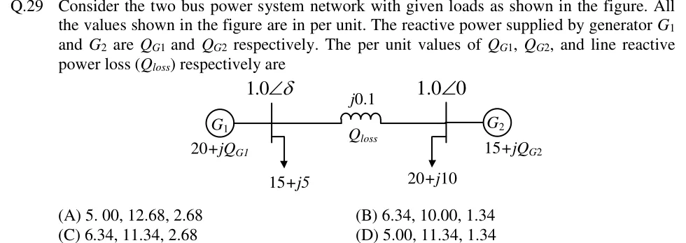
Consider the two bus power system network with given loads as shown in the figure. All the values shown in the figure are in per unit. The reactive power supplied by generator G1 and G2 are Q_G1 and Q_G2 respectively. The per unit values of Q_G1, Q_G2, and line reactive power loss (Q_loss) respectively are

GATE 2018 EE question 29: Single-line diagram of two buses joined by a line of reactance j0.1 pu, with the line reactive loss labelled Q_loss.Tap to open full size
Figure from the GATE 2018 EE paper. It is part of the question.
Figure description

Single-line diagram of two buses joined by a line of reactance j0.1 pu, with the line reactive loss labelled Q_loss. Bus 1 (left) has voltage 1.0∠δ, generator G1 supplying 20+jQ_G1, and a load of 15+j5. Bus 2 (right) has voltage 1.0∠0, generator G2 supplying 15+jQ_G2, and a load of 20+j10.

  1. (A)

    5.00, 12.68, 2.68

  2. (B)

    6.34, 10.00, 1.34

  3. (C)

    6.34, 11.34, 2.68

  4. (D)

    5.00, 11.34, 1.34

Answer and solution
GATE 2018 EE Q.29: answer and solution

PRACTICE

6 questions to test yourself

PRACTICE 11 mark · NAT

A three-phase system uses a base of 100 MVA and 11 kV (line-to-line). A per-phase impedance of at this voltage level is expressed in per unit on this base. Find its value, correct to three decimal places.

Answer and solution

Answer: (accepted range )

  1. .

  2. .

PRACTICE 21 mark · MCQ

A power system has 6 buses: one slack bus, two PV buses and three PQ buses. What is the order of the Jacobian matrix in the Newton-Raphson load flow in polar coordinates?

  1. (A)

    10

  2. (B)

    8

  3. (C)

    9

  4. (D)

    7

Answer and solution

Answer: (B)

  1. , .

  2. Order .

  3. Check: is (5 angles), is (3 PQ buses), total .

PRACTICE 31 mark · MSQ

A power network is made of transmission lines and nominal-ratio transformers only (no off-nominal taps, no phase shifters, no mutual coupling). Its bus admittance matrix is formed by inspection. Which of the following statements are correct?

  1. (A)

    is symmetric.

  2. (B)

    The diagonal element is the sum of all admittances connected to bus , including shunt elements.

  3. (C)

    when there is no element directly connecting buses and .

  4. (D)

    Each row of sums to zero irrespective of shunt elements.

Answer and solution

Answer: (A), (B), (C)

  1. A is correct: with no phase shifters .

  2. B is correct by the rule for building the diagonal.

  3. C is correct: off-diagonal elements come only from direct connections.

  4. D is false: a row sums to the shunt admittance at that bus, which is nonzero when shunts exist.

PRACTICE 42 marks · NAT

A three-bus network has a line between buses 1 and 2 of series impedance pu and a line between buses 2 and 3 of series impedance pu. A shunt capacitor of admittance pu is connected at bus 2. Find the imaginary part of in pu (give the signed value).

Answer and solution

Answer: (accepted range )

  1. and .

  2. .

  3. , so the imaginary part is .

PRACTICE 52 marks · MCQ

In a Gauss-Seidel load flow, the present voltage at a load bus is and one plain Gauss-Seidel update gives pu. With an acceleration factor of 1.4, what is the accelerated voltage?

  1. (A)

  2. (B)

  3. (C)

  4. (D)

Answer and solution

Answer: (A)

  1. .

  2. .

  3. .

PRACTICE 61 mark · NAT

In a DC load flow of a two-bus system, bus 1 is the slack with , and the line between the buses has reactance pu. The solved angle at bus 2 is rad. Find the real power flow from bus 1 to bus 2, in pu.

Answer and solution

Answer: (accepted range )

  1. .

  2. pu.

OFFICIAL GATE 2027 SYLLABUS WORDING

Copied from the GATE 2027 syllabus; see all 2027 syllabi.

GATE EE

Per‐unit quantities, Bus admittance matrix, Gauss- Seidel and Newton-Raphson load flow methods

Preparing in Kolkata? IAE Academy's course for GATE EE.