
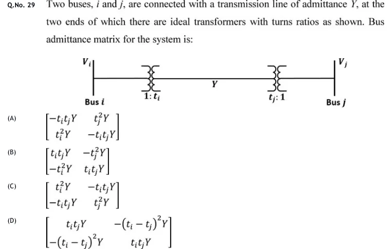
Two buses, and , are connected with a transmission line of admittance , at the two ends of which there are ideal transformers with turns ratios as shown. Bus admittance matrix for the system is:
 Tap to open full size
Figure description
Single-line diagram. Bus i (voltage V_i) on the left, a vertical bus bar. A horizontal line runs from it through an ideal transformer marked 1: t_i, then along the line labelled Y, then through a second ideal transformer marked t_j: 1, to bus j (voltage V_j) on the right, a vertical bus bar.
- (A)
- (B)
- (C)
- (D)