
IAE Academy

GATE 2026 EE Q.41: solution and answer

GATE 2026 · EEQ.41 · 2 marks · MCQ

A three-phase two-winding transformer has a voltage transformation ratio , where is the primary side voltage in p.u., and is the secondary side voltage in p.u. and represent the currents injected into the primary and secondary sides of the transformer, respectively. The admittance corresponding to the leakage impedance of the transformer referred to the secondary is p.u. Neglect the magnetizing branch. The Y bus representation of this transformer is:
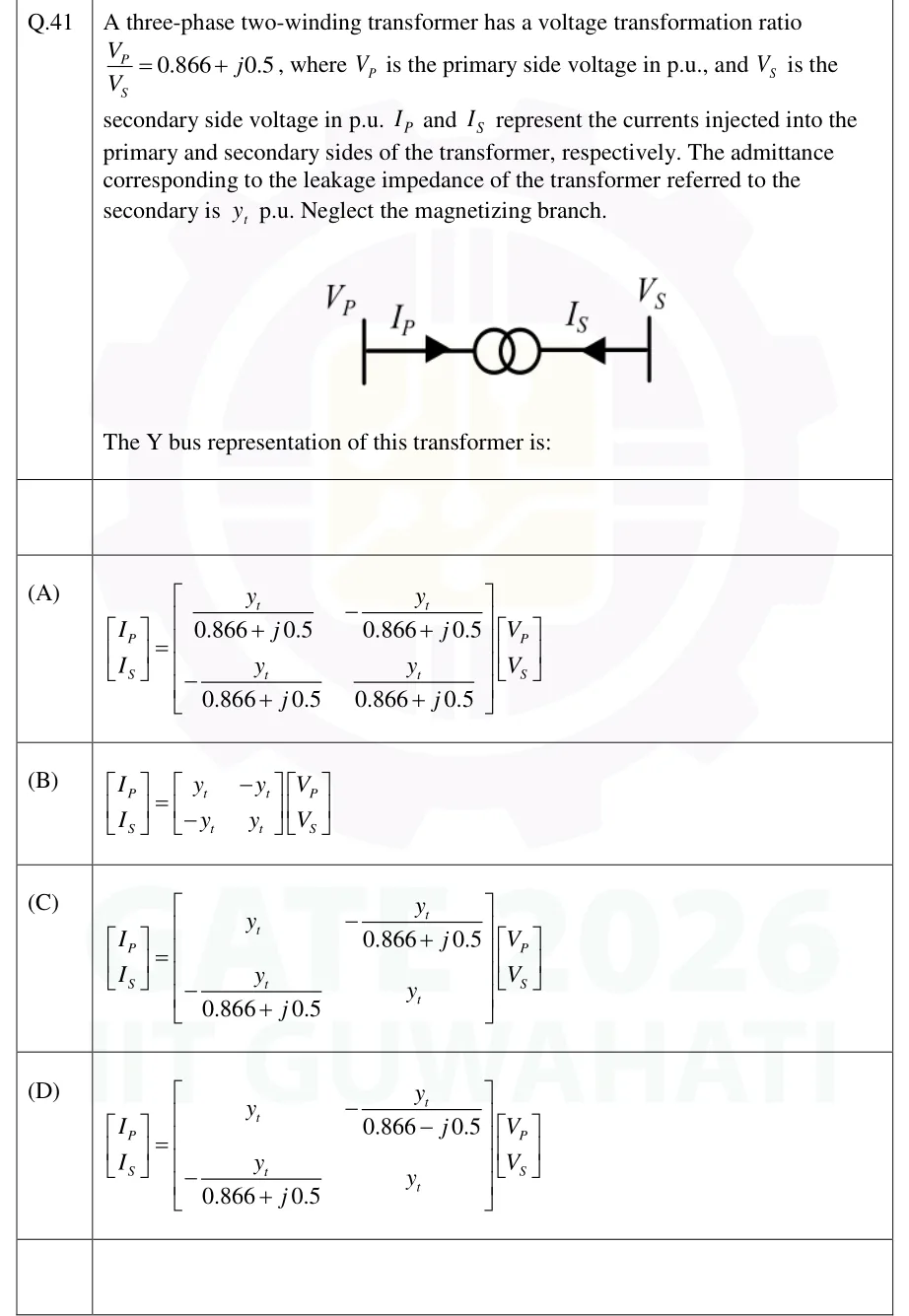
GATE 2026 EE question 41: Single-line diagram of a transformer symbol (two coupled circles) between two bus bars.Tap to open full size
Figure from the GATE 2026 EE paper. It is part of the question.
Figure description

Single-line diagram of a transformer symbol (two coupled circles) between two bus bars. Left bus carries voltage V_P with current I_P drawn by an arrow pointing into the transformer; right bus carries voltage V_S with current I_S drawn by an arrow pointing into the transformer from the right.

  1. (A)

    Figure — [I_P; I_S] = [[ y_t/(0.866+j0.5), -y_t/(0.866+j0.5) ], [ -y_t/(0.866+j0.5), y_t/(0.866+j0.5) ]] [V_P; V_S]

  2. (B)

    Figure — [I_P; I_S] = [[ y_t, -y_t ], [ -y_t, y_t ]] [V_P; V_S]

  3. (C)

    Figure — [I_P; I_S] = [[ y_t, -y_t/(0.866+j0.5) ], [ -y_t/(0.866+j0.5), y_t ]] [V_P; V_S]

  4. (D)

    Figure — [I_P; I_S] = [[ y_t, -y_t/(0.866-j0.5) ], [ -y_t/(0.866+j0.5), y_t ]] [V_P; V_S]

Answer and solution

ANSWER

The Y bus representation is , which is option (D).

Official answer: DSource: Official answer key, GATE 2026 EE (IIT Guwahati)

  1. Let . Then and . The leakage admittance is referred to the secondary, so model the transformer as an ideal complex-ratio transformer on the primary side, followed by the series admittance on the secondary side. All quantities are in p.u.

  2. Let be the voltage on the secondary terminal of the ideal transformer, so that and . The current injected at the secondary bus flows through into this terminal:

  3. An ideal transformer absorbs no net complex power. The current into its primary terminal is and the current into its secondary terminal is , so Taking the conjugate gives .

  4. Substitute from step 2:

  5. Since :

  6. The secondary row, from step 2, is

  7. Collect the two rows: The matrix is not symmetric because the ratio is complex, so the transformer is a phase shifter. This is option (D). Options (A) to (C) are symmetric, so none of them can represent a phase-shifting transformer.

KEY IDEA

A transformer with complex tap ratio , with referred to the secondary, has , , and . Derive it from the series admittance plus an ideal transformer that conserves complex power. The and in the off-diagonal terms make the matrix non-symmetric for a phase shifter.

WATCH OUT FOR

Using the same factor in both off-diagonal terms, or treating the matrix as symmetric as for a real tap ratio. With a complex ratio the current relation is , not , so one off-diagonal term carries the conjugate.

From the GATE 2026 EE paper. Every question of this paper · Download the full paper · All 10 Per unit & load flow questions, with notes

More Per unit & load flow questions