
IAE Academy

GATE 2023 EE Q.41: solution and answer

GATE 2023 · EEQ.41 · 2 marks · MCQ

The three-bus power system shown in the figure has one alternator connected to bus 2 which supplies 200 MW and 40 MVAr power. Bus 3 is infinite bus having a voltage of magnitude |V3| = 1.0 p.u. and angle of -15°. A variable current source, |I|∠φ is connected at bus 1 and controlled such that the magnitude of the bus 1 voltage is maintained at 1.05 p.u. and the phase angle of the source current, φ = θ1 ± π/2, where θ1 is the phase angle of the bus 1 voltage. The three buses can be categorized for load flow analysis as
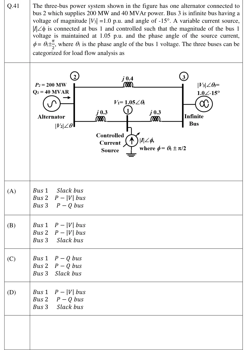
GATE 2023 EE question 41: Single-line diagram of a three-bus system.Tap to open full size
Figure from the GATE 2023 EE paper. It is part of the question.
Figure description

Single-line diagram of a three-bus system. Bus 2 (left vertical bar) has an alternator with P2 = 200 MW, Q2 = 40 MVAR and voltage |V2|∠θ. Bus 3 (right vertical bar) is an infinite bus with |V3|∠θ3 = 1.0∠-15°. Bus 2 and bus 3 are joined by a direct line of reactance j0.4. Bus 1 sits at the midpoint of a lower path: j0.3 from bus 2 to bus 1 and j0.3 from bus 1 to bus 3. At bus 1 the voltage is V1 = 1.05∠θ1, and a controlled current source |I|∠φ, with φ = θ1 ± π/2, is connected from bus 1 to ground.

  1. (A)

    Bus 1: Slack bus; Bus 2: P-|V| bus; Bus 3: P-Q bus

  2. (B)

    Bus 1: P-|V| bus; Bus 2: P-|V| bus; Bus 3: Slack bus

  3. (C)

    Bus 1: P-Q bus; Bus 2: P-Q bus; Bus 3: Slack bus

  4. (D)

    Bus 1: P-|V| bus; Bus 2: P-Q bus; Bus 3: Slack bus

Answer and solution

ANSWER

Bus 1 is a - bus, Bus 2 is a - bus and Bus 3 is the slack bus, which is option (D).

Official answer: DSource: Official answer key, GATE 2023 EE (IIT Kanpur)

  1. In load-flow analysis each bus has four variables, , , and , and two of them are specified. The pair that is specified decides the bus type: and for the slack bus, and for a - bus, and and for a - bus.

  2. Bus 3 is an infinite bus with and both fixed. It is therefore the slack (reference) bus.

  3. Bus 2 has the alternator output fixed at and . Both and are specified, so bus 2 is a - bus.

  4. Bus 1 has voltage and source current . The complex power injected at bus 1 is . With , this gives

  5. The real part of is zero for every value of , so is known. changes with the source current, so it is not specified. is held fixed. With and specified, bus 1 is a - (voltage-controlled) bus.

  6. Result: Bus 1 is a - bus, Bus 2 is a - bus and Bus 3 is the slack bus. This is option (D).

KEY IDEA

A bus is classified by the two quantities held fixed. Check the product for the controlled source. A current out of phase with the bus voltage injects purely reactive power, so is fixed while floats, and with also held the bus is -.

WATCH OUT FOR

Treating bus 1 as - because it carries a current source, or as a slack bus because nothing else is specified there. The angle makes and the voltage magnitude is held at 1.05 p.u., so is the free variable. Another slip is to call bus 2 a - bus just because it has an alternator. Its is given as 40 MVAr and its voltage magnitude is not specified.

From the GATE 2023 EE paper. Every question of this paper · Download the full paper · All 10 Per unit & load flow questions, with notes

More Per unit & load flow questions