
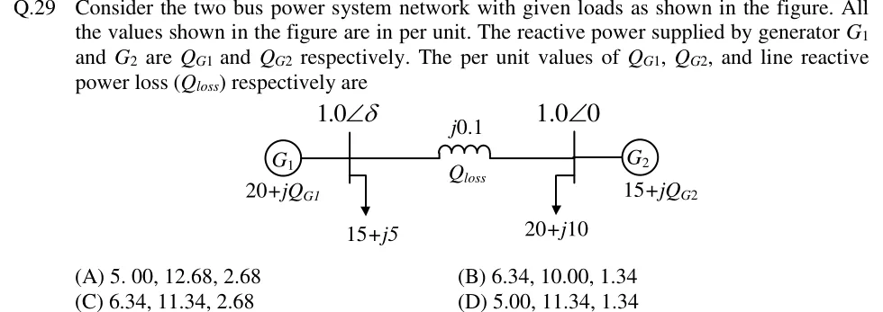
Consider the two bus power system network with given loads as shown in the figure. All the values shown in the figure are in per unit. The reactive power supplied by generator G1 and G2 are Q_G1 and Q_G2 respectively. The per unit values of Q_G1, Q_G2, and line reactive power loss (Q_loss) respectively are
 Tap to open full size
Figure description
Single-line diagram of two buses joined by a line of reactance j0.1 pu, with the line reactive loss labelled Q_loss. Bus 1 (left) has voltage 1.0∠δ, generator G1 supplying 20+jQ_G1, and a load of 15+j5. Bus 2 (right) has voltage 1.0∠0, generator G2 supplying 15+jQ_G2, and a load of 20+j10.
- (A)
5.00, 12.68, 2.68
- (B)
6.34, 10.00, 1.34
- (C)
6.34, 11.34, 2.68
- (D)
5.00, 11.34, 1.34