IAE Academy

GATE EE

Transmission & distribution

Generation, transmission lines, cables, compensation, insulators and distribution

This topic covers how bulk power is generated, carried over AC and HVDC lines and cables, held within voltage limits by compensation, and finally distributed to consumers. The key models and results are GMD and GMR for inductance and capacitance, the ABCD constants of short, medium and long lines, regulation, the Ferranti effect, SIL, series and shunt compensation, cable stress, string efficiency and distributor voltage drop.

6 previous-year questions · 6 solved · 6 practice questions

Generation and the choice between AC and HVDC

A thermal station burns fuel to raise steam, the steam turns a turbine and the turbine drives a synchronous generator. A hydro station turns the head and flow of water into shaft power, so the output is . A nuclear station is a thermal station whose heat source is fission, so its steam cycle and generator are the same in principle. Thermal and nuclear units are run at steady, high loading (base load) because they are slow to change output. Hydro units can start and change load quickly, so they are well suited to meeting peak load.

HYDRO POWER OUTPUT

, , in m/s, net head in m, overall efficiency; result in W.

LOAD FACTOR AND CAPACITY FACTOR

Both over the same period; each is at most 1.

DEMAND FACTOR AND DIVERSITY FACTOR

Individual maximum demands occur at different times, so their sum is at least the group's maximum demand. A higher diversity factor means less plant capacity is needed to supply the same consumers.

AC is used for most transmission because transformers make voltage changes easy. HVDC needs converter stations at both ends, which are costly, but the line itself is cheaper (two conductors for a bipolar line, smaller towers) and has no reactive power or stability limit set by line length. So HVDC pays beyond a break-even distance for overhead lines (the distance is large, of the order of several hundred km), for long submarine or underground cables where AC charging current would be prohibitive, and for linking two asynchronous grids.

Aspect

HVAC

HVDC

Voltage change

Transformer, simple

Converter stations needed

Reactive power and charging current

Present; limits long lines and cables

None on the DC line in steady state; converters absorb reactive power

Stability limit with distance

Power-angle limit falls with length

No angle limit

Skin effect

Present; raises the AC resistance

Absent; the whole conductor section carries current

Interconnecting different frequencies

Not possible

Possible (asynchronous link)

Terminal cost

Low

High

EXAM TIP

Take the same insulation level (the same peak voltage to earth) and the same conductor current rating . A DC conductor carries , while an AC conductor at unity power factor carries . So a bipolar DC line with two conductors () carries about as much power as a three-phase AC line with three (). For short overhead lines HVAC is cheaper, because the converter terminals dominate the cost.

Transmission line parameters: R, L and C

Convention: all line parameters here are per phase, per unit length, for a balanced three-phase line, and is the imaginary unit. The DC resistance is . The AC resistance is higher than the DC resistance because of skin effect and proximity effect, and all resistance rises with temperature. Inductance comes from flux linkage inside and outside the conductor. The geometric mean radius (GMR) of a solid round conductor of radius is . The geometric mean distance (GMD) is the equivalent spacing between the phases. The inductive reactance per phase is .

INDUCTANCE PER PHASE OF A TRANSPOSED THREE-PHASE LINE

is the GMD between phases, the GMR of one phase conductor (self GMD). For a three-phase line, . For a bundled phase, is the bundle GMR from the table below.

CAPACITANCE TO NEUTRAL PER PHASE

Transposed line, ground effect neglected; is the same GMD as for inductance. The capacitance uses the actual radius (or the bundle's equivalent radius built with , not ), because it depends on the surface charge, not on internal flux.

Transposition makes each conductor occupy every position for one third of the length, so the three phases have equal average inductance and capacitance and the line is balanced. Bundling splits each phase into two to four sub-conductors. It raises the effective radius, so it lowers inductance, raises capacitance, reduces corona and lowers the surge impedance, which raises the surge impedance loading.

Bundle (sub-conductor spacing )

GMR for inductance ( = GMR of one sub-conductor)

Two sub-conductors

Three sub-conductors in a triangle

Four sub-conductors in a square

SINGLE-PHASE TWO-WIRE LINE (RADIUS R, SPACING D)

The loop inductance is twice the inductance of one conductor. The line-to-line capacitance is half the capacitance of either conductor to neutral, . Valid for .

EXAM TIP

For the capacitance of a bundle, replace by in the same expressions. The GMD between phases is measured between bundle centres, which is valid when the sub-conductor spacing is small compared with the phase spacing.

Line models, ABCD constants and performance

Phasor convention: voltages and currents are per phase (line-to-neutral) phasors with magnitude and angle, and is the imaginary unit. The line is described by and . Here is the total series impedance and the total shunt admittance. A short line (up to about 80 km) neglects . A medium line (about 80 to 250 km) lumps in a nominal-T or nominal-. A long line (beyond about 250 km) needs the distributed model. The limits are approximate.

Model

Short line

Nominal-

Nominal-T

Long line (exact)

PROPERTIES OF ABCD CONSTANTS

holds for any passive, linear, bilateral two-port, such as a transmission line. holds in addition when the two-port is symmetrical; the short, nominal-, nominal-T and long-line models are all symmetrical.

PROPAGATION CONSTANT AND CHARACTERISTIC IMPEDANCE

and are the series impedance and shunt admittance per unit length.

VOLTAGE REGULATION

held constant; magnitudes per phase (or line-to-line throughout). Multiply by 100 for per cent. For a short line . Regulation can be negative, for example with a leading-power-factor load. Efficiency is at the same load.

RECEIVING-END POWER FROM ABCD CONSTANTS

, , , . With line-to-line voltages the result is three-phase power; with line-to-neutral voltages it is power per phase. For a lossless short line (, ) it reduces to .

LOSSLESS LINE: SURGE IMPEDANCE AND SIL

, per unit length; is the line-to-line voltage; SIL is the total three-phase power at which the line draws zero net reactive power. At SIL the voltage magnitude is the same all along the line. Below SIL the line produces net vars and the receiving voltage tends to rise; above SIL it absorbs vars and the voltage sags.

FERRANTI EFFECT (LOSSLESS, OPEN RECEIVING END)

The receiving-end voltage exceeds the sending-end voltage because the line charging current flows through the series inductance. The approximation holds for small ; it equals with , per unit length, so the rise grows roughly with the square of the length.

POWER-ANGLE RELATION (LOSSLESS LINE)

is the series reactance of the line; is the angle by which leads . Maximum power at is (steady-state limit). Use line-to-line voltages for three-phase power and line-to-neutral voltages for power per phase. For a long lossless line, replace by .

WORKED EXAMPLE

A medium transmission line modelled as a nominal- has total series impedance and total shunt admittance . The sending-end line-to-line voltage is held at 220 kV. Find the ABCD constants and the receiving-end line-to-line voltage at no load.

Solution
  1. .

  2. .

  3. .

  4. .

  5. Check: .

  6. No load (): . The relation is linear and is real, so the same ratio holds for line-to-line magnitudes: kV.

Answer: , , S, and the no-load receiving voltage is about 231.6 kV (about 5.3% above the sending voltage).

EXAM TIP

The ABCD relation uses per-phase voltage. Divide a line-to-line voltage by first, and convert back at the end. A check catches most arithmetic slips.

Underground cables

Convention: single-core cable with conductor radius and inner sheath radius , dielectric of relative permittivity and resistivity , length . The insulation is thin and has , so a cable has a much higher capacitance per unit length than an overhead line, and a lower inductance. Its charging current is therefore large, which limits the length of an AC cable.

CAPACITANCE AND INSULATION RESISTANCE OF A SINGLE-CORE CABLE

The insulation resistance is radial, so it is inversely proportional to the cable length .

DIELECTRIC STRESS IN A CABLE

is the voltage between conductor and sheath (use rms for rms stress), . Stress is greatest at the conductor surface and least at the sheath.

For a given and , is smallest when , that is . This is the most economical conductor radius. Grading makes the stress more uniform. In capacitance grading, layers of dielectric with different permittivities are used, with the highest permittivity nearest the conductor. In intersheath grading, metallic intersheaths placed between the conductor and the sheath are held at chosen intermediate potentials, for example from transformer tappings.

THREE-CORE CABLE: CAPACITANCE PER PHASE

is the core-to-sheath and the core-to-core capacitance. : all three cores bunched, measured against the sheath. : two cores bunched with the sheath, measured against the third core. is the capacitance of each core to neutral; the charging current per phase is .

Series and shunt compensation

Compensation controls reactive power so that voltage stays within limits and more power can be carried. Series compensation inserts a capacitor in the line to cancel part of its inductive reactance. Shunt compensation connects reactors or capacitors across the line to absorb or supply reactive power. Shunt reactors reduce the Ferranti rise and the voltage on lightly loaded lines. Shunt capacitors support voltage on heavily loaded lines. Series capacitors can cause subsynchronous resonance with the shafts of turbine-generators, so the degree of series compensation is limited.

SERIES COMPENSATION

is the degree of series compensation. Then , raised by the factor . Voltage drop and regulation also improve.

REACTIVE POWER OF A SHUNT ELEMENT

A shunt capacitor supplies and a shunt reactor absorbs it. Use and on a consistent basis: per phase with , or three-phase with the line-to-line voltage and star-connected per phase. A capacitor's output falls as , so it gives least support when the voltage is low.

Device

Action

Typical use

Series capacitor

Reduces

Raise transfer capability of a long line

Shunt reactor

Absorbs vars

Light load, long lines, limit Ferranti rise

Shunt capacitor

Supplies vars

Heavy load, power-factor correction

Static var compensator (SVC)

Fast, continuously variable vars (thyristor-controlled reactor with capacitors)

Voltage control, damping swings

EXAM TIP

Series compensation reduces , so in it raises the limit by with the end voltages unchanged. Shunt compensation at the line ends changes the voltages, not . An ideal shunt compensator holding the mid-point voltage at (equal end voltages ) splits the line into two halves of and doubles the limit to .

Insulators and corona

In a suspension string of identical units, each unit has a capacitance and each junction has a shunt capacitance to earth. The charging current through the shunt capacitances makes the voltage across the units unequal. The unit nearest the conductor takes the largest voltage. Let and let be the voltage across the unit nearest the cross-arm.

VOLTAGE ACROSS UNITS OF A THREE-UNIT STRING

Units numbered from the cross-arm end; the total string voltage is (phase-to-earth), and is the largest.

STRING EFFICIENCY

It is at most 100%, reached only if , and it falls as increases. Capacitance grading (units of different capacitance), a guard ring (static shielding) and longer cross-arms (smaller ) all improve it.

Corona is the ionisation of air around a conductor when the surface electric stress exceeds the breakdown strength of air. It causes power loss, radio interference and audible noise. The critical disruptive voltage rises with conductor radius, with air density and with spacing, so bundled conductors of larger effective radius reduce corona.

CRITICAL DISRUPTIVE VOLTAGE (PER PHASE, RMS)

kV/cm rms is the breakdown strength of air at standard conditions, the surface factor, and (spacing) in cm, the pressure in cm of Hg and the temperature in C ( at 76 cm Hg and C). The result is in kV rms, phase to neutral.

Distribution systems

Distribution carries power from substations to consumers. A feeder carries power from the substation to a distribution point with no loads tapped along it, so its current is the same along its length. A distributor has loads tapped along it, so its current changes from section to section, and it is designed for voltage drop. A radial system has a single path, so it is simple and cheap, but a fault cuts off every load beyond it. A ring main is a closed loop fed at one or more points, so a consumer can be supplied from either side. It costs more but gives better continuity. Voltage drop along a distributor is calculated from the section currents and the resistance and reactance of each section.

APPROXIMATE VOLTAGE DROP OF A SECTION (PER PHASE)

Lagging load of power factor and current ; and are the per-phase resistance and reactance of the section. Valid when the angle between the two end voltages is small. A leading load makes the term negative.

UNIFORMLY LOADED DISTRIBUTOR FED AT ONE END

Load current per unit length constant along the whole length, at unity power factor (or DC). is the total load current and the distributor resistance (the loop resistance of both conductors for a two-wire DC or single-phase distributor). The drop is half that of the same total current concentrated at the far end.

UNIFORMLY LOADED DISTRIBUTOR FED AT BOTH ENDS WITH EQUAL VOLTAGES

Same symbols and conditions as above. The minimum voltage is at the mid-point.

  1. Name the section currents. With resistive loads, the point of minimum voltage is the load point where the currents from the two sides meet.

  2. For a ring main with a single feed, cut the ring at the feed point and treat it as a distributor fed at both ends with equal voltages.

  3. Find the current in each section by superposition (one source at a time) or by KVL. With equal end voltages, the section drops from one feed point to the other add up to zero.

  4. Add up section drops from the feed to the load for each branch, with sign for current direction.

Kelvin's law: the most economical conductor cross-section is the one for which the annual cost of the energy lost in the conductor equals the annual interest and depreciation on the part of the capital cost that is proportional to the cross-section.

EXAM TIP

In a distributor fed at both ends with equal end voltages, the point of minimum potential is not in the middle unless the loads are symmetrical. Find it from the current split, not by assumption.

PREVIOUS-YEAR QUESTIONS

6 questions from the EE papers

Try each question first, then open the answer. We placed each question under a topic ourselves; the exam paper does not label topics.

See these papers in full: GATE EE 2026 · GATE EE 2025 · GATE EE 2024 · GATE EE 2023 · GATE EE 2022 · GATE EE 2020

GATE 2026 EE Q.54

GATE 2026 · EEQ.54 · 2 marks · MSQ

For the balanced 3-phase transmission line shown, consider the following cases: Case-1: p.u., p.u., p.u. and . Case-2: p.u., p.u., p.u. and . Which of the following statements is/are correct about real power loss and reactive power loss in the line?
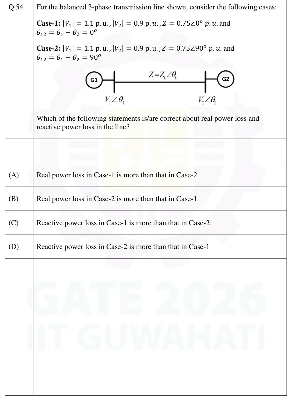
GATE 2026 EE question 54: Single-line diagram: generator G1 (circle) connected to a bus on the left with voltage V1∠θ1, a horizontal transmission…Tap to open full size
Figure from the GATE 2026 EE paper. It is part of the question.
Figure description

Single-line diagram: generator G1 (circle) connected to a bus on the left with voltage V1∠θ1, a horizontal transmission line labelled Z = Z_L∠θ_L joining to a bus on the right with voltage V2∠θ2, connected to generator G2 (circle).

  1. (A)

    Real power loss in Case-1 is more than that in Case-2

  2. (B)

    Real power loss in Case-2 is more than that in Case-1

  3. (C)

    Reactive power loss in Case-1 is more than that in Case-2

  4. (D)

    Reactive power loss in Case-2 is more than that in Case-1
Answer and solution
GATE 2026 EE Q.54: answer and solution

GATE 2024 EE Q.19

GATE 2024 · EEQ.19 · 1 mark · MCQ

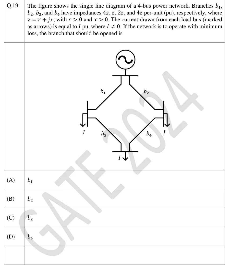
The figure shows the single line diagram of a 4-bus power network. Branches b1, b2, b3, and b4 have impedances 4z, z, 2z, and 4z per-unit (pu), respectively, where z = r + jx, with r > 0 and x > 0. The current drawn from each load bus (marked as arrows) is equal to I pu, where I ≠ 0. If the network is to operate with minimum loss, the branch that should be opened is

GATE 2024 EE question 19: A generator (source) feeds a top bus.Tap to open full size
Figure from the GATE 2024 EE paper. It is part of the question.
Figure description

A generator (source) feeds a top bus. Branch b1 (4z) runs from the top bus to the left load bus (load I). Branch b2 (z) runs from the top bus to the right load bus (load I). Branch b3 (2z) connects the left load bus to the bottom load bus (load I). Branch b4 (4z) connects the right load bus to the bottom load bus. The network is a ring: source, left bus, bottom bus, right bus. Each of the three load buses draws current I.

  1. (A)

    b1

  2. (B)

    b2

  3. (C)

    b3

  4. (D)

    b4

Answer and solution
GATE 2024 EE Q.19: answer and solution

GATE 2023 EE Q.33

GATE 2023 · EEQ.33 · 1 mark · NAT

A 50 Hz, 275 kV line of length 400 km has the following parameters: Resistance, R = 0.035 Ω/km; Inductance, L = 1 mH/km; Capacitance, C = 0.01 μF/km. The line is represented by the nominal-π model. With the magnitudes of the sending end and the receiving end voltages of the line (denoted by V_S and V_R, respectively) maintained at 275 kV, the phase angle difference (θ) between V_S and V_R required for maximum possible active power to be delivered to the receiving end, in degree is ______ (Round off to 2 decimal places).

Answer and solution
See the question in the paper
GATE 2023 EE Q.33: answer and solution

GATE 2022 EE Q.14

GATE 2022 · EEQ.14 · 1 mark · MCQ

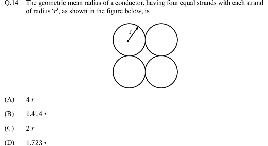
The geometric mean radius of a conductor, having four equal strands with each strand of radius 'r', as shown in the figure below, is

GATE 2022 EE question 14: Four equal circles of radius r, each touching its neighbours, arranged as a 2 x 2 square: two circles on top, two below.Tap to open full size
Figure from the GATE 2022 EE paper. It is part of the question.
Figure description

Four equal circles of radius r, each touching its neighbours, arranged as a 2 x 2 square: two circles on top, two below. The top-left circle shows its centre as a dot with an arrow marking the radius r. Centre-to-centre spacing is 2r along the sides and 2 sqrt(2) r along the diagonals.

  1. (A)

    4 r

  2. (B)

    1.414 r

  3. (C)

    2 r

  4. (D)

    1.723 r

Answer and solution
GATE 2022 EE Q.14: answer and solution

GATE 2020 EE Q.47

GATE 2020 · EEQ.47 · 2 marks · NAT

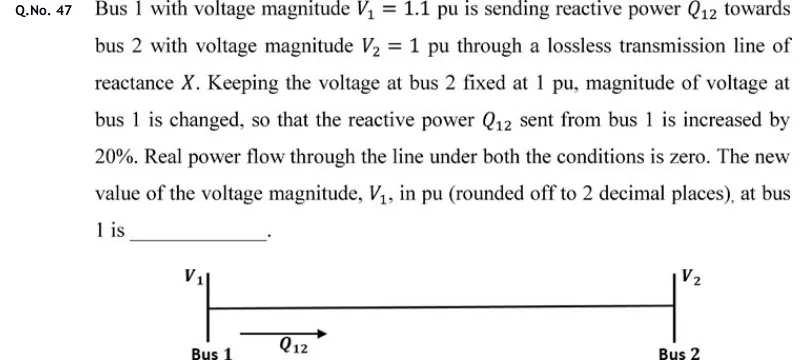
Bus 1 with voltage magnitude pu is sending reactive power towards bus 2 with voltage magnitude pu through a lossless transmission line of reactance . Keeping the voltage at bus 2 fixed at 1 pu, magnitude of voltage at bus 1 is changed, so that the reactive power sent from bus 1 is increased by 20%. Real power flow through the line under both the conditions is zero. The new value of the voltage magnitude, , in pu (rounded off to 2 decimal places), at bus 1 is ______.

GATE 2020 EE question 47: Single-line diagram: a horizontal line joining Bus 1 (left, voltage V_1) and Bus 2 (right, voltage V_2), with an arrow…Tap to open full size
Figure from the GATE 2020 EE paper. It is part of the question.
Figure description

Single-line diagram: a horizontal line joining Bus 1 (left, voltage V_1) and Bus 2 (right, voltage V_2), with an arrow below the line near Bus 1 labelled Q_12 pointing from bus 1 towards bus 2.

Answer and solution
GATE 2020 EE Q.47: answer and solution

PRACTICE

6 questions to test yourself

PRACTICE 11 mark · NAT

A lossless three-phase transmission line has and per phase. Its line-to-line operating voltage is 400 kV. Find its surge impedance loading in MW.

Answer and solution

Answer: (accepted range )

  1. .

  2. W.

  3. SIL is about 506 MW.

PRACTICE 22 marks · NAT

A lossless three-phase line has a series reactance of 80 per phase. Both end voltages are 400 kV line-to-line. The line is compensated by a series capacitor giving 25% compensation, and the angle between the end voltages is . Find the three-phase real power transferred, in MW.

Answer and solution

Answer: (accepted range )

  1. .

  2. MW (line-to-line in kV and in give three-phase MW).

  3. MW.

PRACTICE 31 mark · MSQ

Which of the following statements about the Ferranti effect on a long, lossless, three-phase line are correct?

  1. (A)

    It is seen when the line is open-ended or very lightly loaded.

  2. (B)

    It is caused by the line charging current flowing through the series inductance of the line.

  3. (C)

    The receiving-end voltage is always lower than the sending-end voltage.

  4. (D)

    Shunt reactors connected at the receiving end reduce the rise.

Answer and solution

Answer: (A), (B), (D)

  1. At light load the line current is mainly the charging current, which leads by . The voltage across the series reactance is then in antiphase with , so . A and B are correct.

  2. The receiving-end voltage is higher than the sending-end voltage, so C is false.

  3. Shunt reactors absorb the charging vars and reduce the rise, so D is correct. The answer is A, B and D.

PRACTICE 42 marks · MCQ

A suspension insulator string has three identical units. The ratio of shunt capacitance of each junction to the capacitance of a unit is . What is the string efficiency?

  1. (A)

    77.0%

  2. (B)

    86.8%

  3. (C)

    91.2%

  4. (D)

    95.0%

Answer and solution

Answer: (B)

  1. With at the cross-arm unit, and .

  2. Total .

  3. Efficiency , which is 86.8%.

PRACTICE 52 marks · NAT

A single-core cable has a conductor radius of 1 cm and an inner sheath radius of 4 cm. The rms voltage between the conductor and the sheath is 33 kV. Find the maximum dielectric stress in kV/cm (rms).

Answer and solution

Answer: (accepted range )

  1. .

  2. .

  3. kV/cm.

PRACTICE 61 mark · NAT

A two-wire DC distributor of length 2 km has a loop resistance (both conductors together) of 0.5 /km. It supplies a uniformly distributed load of 100 A per km along its whole length and is fed at one end. Find the total voltage drop from the feeding point to the far end, in volts.

Answer and solution

Answer: (accepted range )

  1. Total load current A.

  2. Total loop resistance .

  3. Drop for a uniformly distributed load fed at one end V.

OFFICIAL GATE 2027 SYLLABUS WORDING

Copied from the GATE 2027 syllabus; see all 2027 syllabi.

GATE EE

Basic concepts of electrical power generation, AC and DC transmission concepts, Models and performance of transmission lines and cables … Series and shunt compensation, Electric field distribution and insulators, Distribution systems

Preparing in Kolkata? IAE Academy's course for GATE EE.