
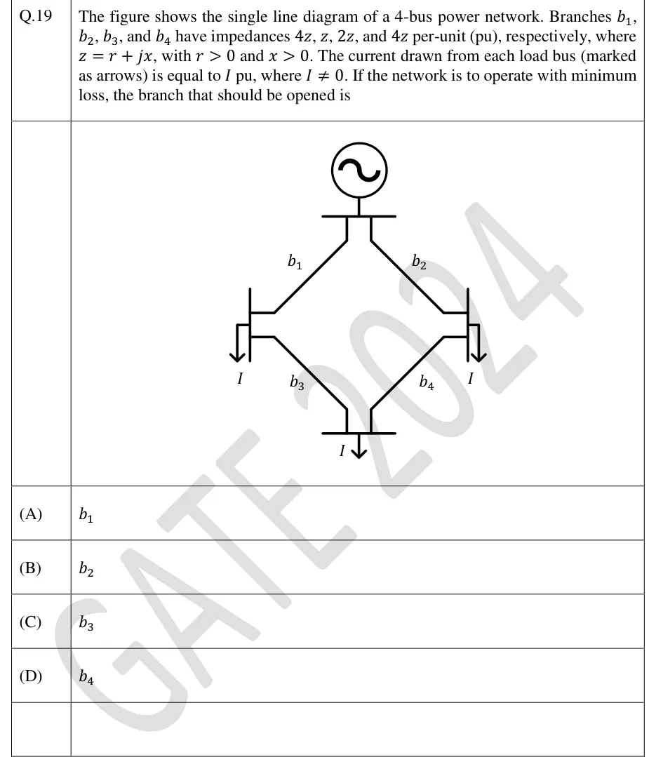
The figure shows the single line diagram of a 4-bus power network. Branches b1, b2, b3, and b4 have impedances 4z, z, 2z, and 4z per-unit (pu), respectively, where z = r + jx, with r > 0 and x > 0. The current drawn from each load bus (marked as arrows) is equal to I pu, where I ≠ 0. If the network is to operate with minimum loss, the branch that should be opened is
 Tap to open full size
Figure description
A generator (source) feeds a top bus. Branch b1 (4z) runs from the top bus to the left load bus (load I). Branch b2 (z) runs from the top bus to the right load bus (load I). Branch b3 (2z) connects the left load bus to the bottom load bus (load I). Branch b4 (4z) connects the right load bus to the bottom load bus. The network is a ring: source, left bus, bottom bus, right bus. Each of the three load buses draws current I.
- (A)
b1
- (B)
b2
- (C)
b3
- (D)
b4