IAE Academy

GATE EE

Protection and circuit breakers

Protection detects a fault, picks out the faulty element and trips only the breakers that must open, so the rest of the system keeps running. Typical numerical problems ask you to set an overcurrent relay (PSM, TMS, IDMT time), balance CTs for a differential scheme, convert a line impedance to the relay's secondary ohms, and size a circuit breaker by its breaking and making capacity.

5 previous-year questions · 4 solved · 5 practice questions

Protection principles and instrument transformers

A protection system has a relay (decides), an instrument transformer (feeds the relay a scaled-down current or voltage) and a circuit breaker (interrupts the fault current). The system is divided into protection zones, one for each generator, transformer, bus and line. Zones overlap, so that no element is left unprotected.

Requirements of a protection scheme

  1. Selectivity: trip only the breakers nearest the fault, so the smallest possible part of the system is disconnected.

  2. Sensitivity: operate for the smallest fault current in the protected zone, including a fault through some resistance.

  3. Speed: clear the fault fast enough to limit damage and keep the system stable.

  4. Reliability: operate when it must, and not operate when it must not (for example on a through fault or magnetising inrush).

  5. Primary protection acts first in its own zone. Backup protection acts only if the primary fails, and it is deliberately delayed so that the primary gets the first chance.

A current transformer (CT) has its primary in series with the line and a secondary feeding a low-impedance burden (the relay coils), rated 1 A or 5 A. A voltage transformer (VT) has its primary across the line and a secondary of about 110 V line to line. The CT ratio is defined here as primary current divided by secondary current, and the VT ratio as primary voltage divided by secondary voltage.

RELAY (SECONDARY) QUANTITIES

N_CT = CT ratio and N_VT = VT ratio, each as primary over secondary. Z_pri is the impedance in primary ohms, from the primary voltage and current.

EXAM TIP

Never leave a CT secondary open-circuited while the primary carries current. Nothing opposes the flux from the primary ampere-turns, so a dangerously high voltage appears across the open secondary. Never short-circuit a VT secondary. If the CT core saturates during a heavy through fault, its secondary current is distorted and falls below the ideal value. This is a common cause of false differential operation.

Overcurrent relays and grading

An overcurrent relay picks up when the current through it exceeds its plug setting (PS). The PS is a percentage of the relay's rated current, which equals the CT secondary rating: for example, 125 % of 5 A = 6.25 A. The time multiplier setting (TMS) sets how fast the relay operates above pickup.

PLUG SETTING MULTIPLIER

Pickup current = plug setting (as a fraction) times the CT rated secondary current. The relay operates only if PSM > 1.

IDMT OPERATING TIME (IEC STANDARD CURVES)

k and alpha depend on the characteristic (table below). Time is in seconds, and the TMS scales the TMS = 1 curve linearly. If a problem gives its own curve, or a table of operating times against PSM for TMS = 1, read the time from it and multiply by the TMS.

Characteristic

k

alpha

Operating time

Standard (normal) inverse

0.14

0.02

TMS x 0.14 / (PSM^0.02 - 1)

Very inverse

13.5

1

TMS x 13.5 / (PSM - 1)

Extremely inverse

80

2

TMS x 80 / (PSM^2 - 1)

Long-time inverse

120

1

TMS x 120 / (PSM - 1)

Inverse means that the larger the current, the shorter the operating time. Definite-time relays operate after a fixed delay once the current is above pickup. Instantaneous relays have no intentional delay.

Grading (coordination) of overcurrent relays on a radial feeder

  1. Start at the relay farthest from the source. It can have the lowest TMS and the lowest settings.

  2. Find the largest fault current that flows through both this relay and the next relay upstream. This is the current for a fault just beyond the downstream relay's breaker. Find the downstream relay's operating time at that current.

  3. Set the upstream relay so that, at the same fault current, its time is longer by a grading margin. The margin covers the breaker opening time, the relay's overshoot and a safety allowance, and is typically a few tenths of a second.

  4. Repeat towards the source. The relay nearest the source has the highest settings and the longest time.

WORKED EXAMPLE

A 400/5 A CT feeds an IDMT (standard inverse) relay set at plug setting 125 % and TMS 0.3. Find the operating time for a primary fault current of 4000 A.

Solution
  1. CT ratio = 400/5 = 80. Secondary fault current = 4000/80 = 50 A.

  2. Pickup current = 1.25 x 5 = 6.25 A.

  3. PSM = 50/6.25 = 8.

  4. 8^0.02 = e^(0.02 x ln 8) = e^(0.04159) = 1.04247, so the denominator is 0.04247.

  5. t = 0.3 x 0.14 / 0.04247 = 0.989 s.

Answer: About 0.99 s

Directional and differential protection

On a ring main or on parallel feeders, fault current can flow either way through a relay. A directional relay compares the current with a reference (polarising) voltage and operates only when the current flows in the tripping direction. Its torque is proportional to the voltage, the current and the cosine of the angle between the current and the relay's maximum-torque line.

DIRECTIONAL ELEMENT TORQUE

phi = angle by which the current I lags the polarising voltage V. tau = the relay's maximum-torque angle, measured the same way. The torque is positive, so the relay can operate, for -90 deg < phi - tau < 90 deg. In practice the torque must also overcome a small restraining (spring) torque.

Differential protection compares the current entering a zone with the current leaving it. In a healthy zone, or during an external (through) fault, the two currents match and the difference is nearly zero. During an internal fault the difference is large and the relay trips. It is unit protection: it responds only to faults inside the CTs that bound the zone.

CT mismatch and saturation produce a spurious difference current during a heavy through fault. The percentage (biased) differential relay counters this. Its operating coil carries the difference current and its restraining coils carry the average (through) current, so the current needed to trip rises as the through current rises.

PERCENTAGE DIFFERENTIAL RELAY

I_1 and I_2 are the CT secondary current phasors at the two ends, both taken in the same sense through the zone. K is the slope (bias) setting, for example 0.2 for 20 %. A small minimum pickup is usually added.

Differential protection of a star-delta transformer

  1. Choose CT ratios so that, for through load, the currents reaching the relay from the two sides are equal once the CT connections are allowed for.

  2. Connect the CTs on the delta-winding side in star, and the CTs on the star-winding side in delta. This compensates for the power transformer's 30 degree phase shift. It also keeps zero-sequence current from an external earth fault out of the relay.

  3. A delta-connected CT set delivers a relay current of sqrt(3) times the CT secondary phase current. Its CT ratio must therefore be sqrt(3) times larger than a star-connected set on the same side would need.

  4. Magnetising inrush at switch-on flows on one side only and looks like an internal fault. It is rich in the second harmonic, which is used to restrain the relay. Overexcitation produces a large fifth-harmonic current, which is used to block the relay. The relay is also biased so that it rides through the through-fault mismatch caused by tap changing.

CT RATIO BALANCE, DELTA-STAR TRANSFORMER

I_L,Delta = line current on the power transformer's delta-winding side, whose CTs are in star. I_L,Y = line current on the star-winding side, whose CTs are in delta. N = ratio of each CT set, primary over secondary. Both sides refer to the same through load.

EXAM TIP

To balance the two sides, equate the currents that reach the relay. A star-connected CT set gives I_line/N_CT. A delta-connected CT set gives sqrt(3) x I_line/N_CT. The delta-connected set always picks up the extra sqrt(3), whichever winding it is on.

WORKED EXAMPLE

A 10 MVA, 33/11 kV delta-star transformer is protected by a differential relay. The CTs on the 33 kV (delta) side are connected in star and have a ratio of 200/5. Find the ratio (primary current/secondary current) of the delta-connected CTs on the 11 kV side so that the relay currents balance.

Solution
  1. 33 kV line current = 10e6 / (sqrt(3) x 33e3) = 174.95 A.

  2. 11 kV line current = 10e6 / (sqrt(3) x 11e3) = 524.86 A.

  3. 33 kV side CT ratio = 200/5 = 40, so the relay current = 174.95/40 = 4.374 A.

  4. The 11 kV CT set is in delta, so the relay current = sqrt(3) x 524.86 / N.

  5. Set sqrt(3) x 524.86 / N = 4.374, which gives N = 909.1/4.374 = 207.8.

Answer: CT ratio about 208 (for example 1040/5 A)

Distance protection

A distance relay compares the voltage and current at its location and measures the apparent impedance, . For a bolted fault on a uniform line, and with the right voltage-current pair for the fault type, this impedance is proportional to the distance to the fault. The relay operates when Z falls inside a characteristic drawn on the R-X plane. Because the relay is set in secondary ohms, the line impedance must be converted using the CT and VT ratios.

Relay

R-X characteristic

Operates when

Directional?

Typical use

Impedance

Circle centred on the origin, radius Zr

|Z| < Zr

No: it also sees faults behind it unless a directional unit is added

Medium-length lines

Reactance

Straight line parallel to the R axis at X = Xr

X < Xr

No: it needs a directional (mho) starting unit, or it would also operate on load

Short lines: it ignores the resistive part of Z, so fault arc resistance does not affect it

Mho (admittance)

Circle through the origin, diameter Zr along the maximum-torque angle

Z inside the circle

Yes, inherently

Long lines; least affected by power swings of the three

MHO CHARACTERISTIC

Z_r = relay reach (the diameter) along the maximum-torque angle tau. theta = angle of the measured impedance. The reach shrinks as the impedance angle moves away from tau. j is the imaginary unit.

UNIVERSAL RELAY TORQUE EQUATION

theta = angle by which I lags V, so Z = V/I at angle theta. K_4 (spring restraint) is neglected in the three special cases. Here a negative constant restrains and a positive one operates.

IMPEDANCE SEEN FOR PHASE AND EARTH FAULTS

x = distance to a bolted fault, Z_1 and Z_0 = positive- and zero-sequence line impedance per unit length, phasor quantities measured at the relay. The phase pair (b, c) works for any fault involving those two phases. The earth-fault element on phase a needs the residual compensation k_0, or it measures the wrong distance.

Zones of a step-distance scheme (typical settings)

  1. Zone 1: about 80 to 90 % of the protected line, instantaneous. It stops short of the far bus to allow for errors in the line impedance data and in the CT and VT.

  2. Zone 2: the whole protected line plus part (about half) of the shortest adjacent line, with a short time delay. It covers the end of the line that Zone 1 leaves out.

  3. Zone 3: the protected line plus the whole of the longest adjacent line, and more, with a longer delay. It is backup for the adjacent lines.

WORKED EXAMPLE

A 100 km line has a positive-sequence impedance of 0.4 ohm/km. It is protected by a distance relay fed from an 800/5 A CT and a 220 kV/110 V VT. Zone 1 is set at 80 % of the line. Find the Zone-1 setting in secondary ohms.

Solution
  1. Line impedance magnitude = 100 x 0.4 = 40 ohm (primary).

  2. Zone 1 = 0.8 x 40 = 32 ohm (primary).

  3. N_CT = 800/5 = 160. N_VT = 220000/110 = 2000.

  4. Z_sec = 32 x 160/2000 = 2.56 ohm.

Answer: 2.56 ohm (secondary)

Circuit breakers

A circuit breaker opens and closes the circuit under normal and fault conditions. When its contacts part, an arc forms between them. In an ac breaker the arc goes out at a current zero. It can re-strike if the voltage building up across the gap rises faster than the gap recovers its dielectric strength. A breaker must therefore deionise and cool the arc path, and in many designs it also lengthens the arc.

Arc interruption and recovery voltage

  1. Arc voltage is the voltage across the arc while current flows. After current zero the supply voltage returns across the gap as the recovery voltage, which is power-frequency in the steady state.

  2. The restriking voltage is the transient part. It oscillates at the natural frequency of the circuit's inductance and capacitance and is superimposed on the recovery voltage immediately after current zero.

  3. The rate of rise of restriking voltage (RRRV) is the key quantity. The arc stays out if the gap's dielectric strength rises faster than the restriking voltage.

  4. High-resistance interruption raises the arc resistance until the current falls to zero; it is used mainly in dc and low-voltage breakers. Low-resistance (current-zero) interruption is used for ac: the arc is put out at a natural current zero.

  5. Resistance switching places a resistor across the contacts to damp the restriking transient. The oscillation disappears when the resistance is no more than the critical value.

  6. Current chopping: a breaker with strong quenching (vacuum, air-blast) can force a small inductive current, such as a transformer's magnetising current, to zero before its natural zero. The trapped magnetic energy then charges the stray capacitance, giving a prospective overvoltage (from ), where i is the chopped current.

RESTRIKING VOLTAGE (UNDAMPED LC)

Assumes resistance is neglected and the system voltage is constant during the transient (f_n is much higher than the supply frequency). V_m = system voltage across the pole at current zero; for a purely inductive fault circuit this is the peak phase voltage. L and C = inductance and capacitance of the circuit seen from the breaker. The peak occurs at t = pi/omega_n and the maximum RRRV at t = pi/(2 omega_n). The average RRRV up to the peak is 2V_m/(pi/omega_n) = 4 V_m f_n.

CRITICAL DAMPING RESISTANCE

For the source inductance L in series, with a resistor R across the contacts in parallel with the capacitance C. If R <= R_crit, the restriking voltage is non-oscillatory.

BREAKING AND MAKING CAPACITY (THREE-PHASE)

V_L = rated line voltage in kV. I_b = rated symmetrical (rms) breaking current in kA. Breaking capacity is in MVA. The making current is the peak of the first current loop, about 1.8 x sqrt(2) = 2.55 times the symmetrical rms breaking current. If the current at contact separation has a dc component I_dc, the asymmetrical rms breaking current is sqrt(I_b^2 + I_dc^2).

Type

Quenching medium

Remarks

Oil circuit breaker

Hydrogen-rich gas from decomposed oil

Older design, fire risk

Air-blast

Compressed air blown across the arc

Fast, noisy, needs a compressor

SF6

Sulphur hexafluoride gas: strongly electronegative, high dielectric strength

Common at high and extra-high voltage

Vacuum

No medium; metal vapour from the contacts diffuses quickly

Widely used at medium voltage, low maintenance

A fuse is a thin element that melts when the current is large enough. Fusing factor = minimum fusing current / current rating, which is always greater than 1. The prospective current is the current that would flow if the fuse were replaced by a solid link. The cut-off current is the highest instantaneous current actually reached. A current-limiting fuse melts and limits the current before the prospective current reaches its first peak, so its cut-off current is below the prospective peak.

EXAM TIP

Breaking capacity is quoted in MVA for the symmetrical rms current, whereas making capacity is a peak current in kA. Do not mix these up. The current actually interrupted at contact separation can include a dc component (the asymmetrical breaking current), so it can exceed the symmetrical rms value.

PREVIOUS-YEAR QUESTIONS

5 questions from the EE papers

Try each question first, then open the answer. We placed each question under a topic ourselves; the exam paper does not label topics.

See these papers in full: GATE EE 2026 · GATE EE 2023 · GATE EE 2022 · GATE EE 2020

GATE 2026 EE Q.39

GATE 2026 · EEQ.39 · 2 marks · MCQ

In the circuit shown, the phase currents are A, A, A. Given that the CTs are ideal with no saturation, and the turns ratio of the Main CT is 300:5 and that of the Auxiliary Transformer (YnΔ) is 2:1 on every phase, the value of , rounded off to three decimal places, is:
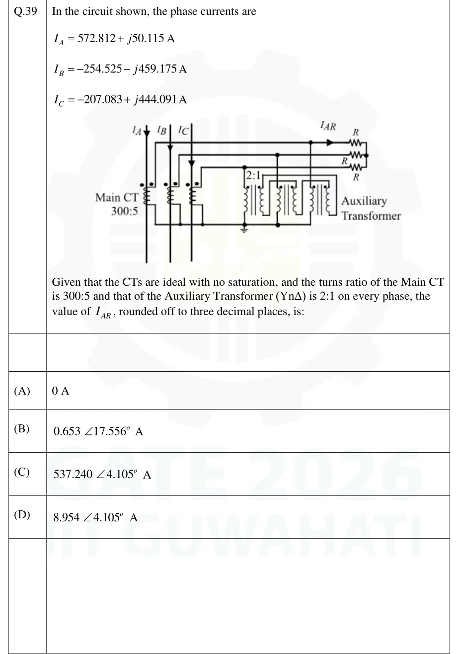
GATE 2026 EE question 39: Three phase conductors carrying I_A, I_B, I_C pass through three Main CTs (300:5).Tap to open full size
Figure from the GATE 2026 EE paper. It is part of the question.
Figure description

Three phase conductors carrying I_A, I_B, I_C pass through three Main CTs (300:5). The CT secondaries are star-connected: one end of each secondary goes to a common bottom bus, which is earthed. The other end of each goes out on its own lead to one of three relay resistors R, and the three R are star-connected at the right with their star point isolated. The current in the phase-A lead is I_AR. An Auxiliary Transformer (YnΔ, 2:1 on every phase) is connected in shunt: each star primary winding is connected from one lead to the earthed common bus, and the delta secondary windings are closed on themselves with no external load.

  1. (A)

    0 A

  2. (B)

    0.653 ∠17.556° A

  3. (C)

    537.240 ∠4.105° A

  4. (D)

    8.954 ∠4.105° A

Official answer
GATE 2026 EE Q.39: official answer

GATE 2026 EE Q.40

GATE 2026 · EEQ.40 · 2 marks · MCQ

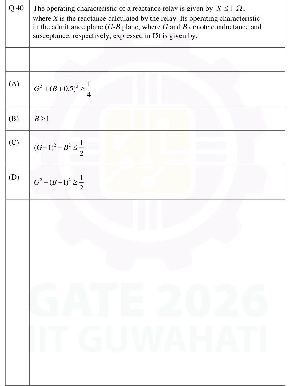
The operating characteristic of a reactance relay is given by X ≤ 1 Ω, where X is the reactance calculated by the relay. Its operating characteristic in the admittance plane (G-B plane, where G and B denote conductance and susceptance, respectively, expressed in mho) is given by:

  1. (A)

    G^2 + (B + 0.5)^2 ≥ 1/4

  2. (B)

    B ≥ 1

  3. (C)

    (G − 1)^2 + B^2 ≤ 1/2

  4. (D)

    G^2 + (B − 1)^2 ≥ 1/2

Answer and solution
See the question in the paper
GATE 2026 EE Q.40: answer and solution

GATE 2023 EE Q.20

GATE 2023 · EEQ.20 · 1 mark · MCQ

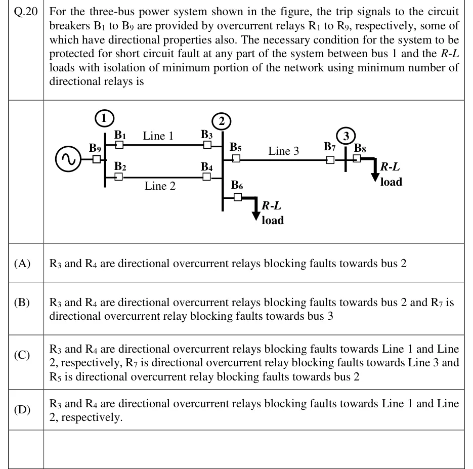
For the three-bus power system shown in the figure, the trip signals to the circuit breakers B1 to B9 are provided by overcurrent relays R1 to R9, respectively, some of which have directional properties also. The necessary condition for the system to be protected for short circuit fault at any part of the system between bus 1 and the R-L loads with isolation of minimum portion of the network using minimum number of directional relays is

GATE 2023 EE question 20: Single-line diagram.Tap to open full size
Figure from the GATE 2023 EE paper. It is part of the question.
Figure description

Single-line diagram. A generator at the left connects through breaker B9 to bus 1. Two parallel lines run from bus 1 to bus 2: Line 1 (top) has B1 at the bus 1 end and B3 at the bus 2 end; Line 2 (bottom) has B2 at the bus 1 end and B4 at the bus 2 end. At bus 2, breaker B5 leads to Line 3, which runs to bus 3 with breaker B7 at the bus 3 end. Breaker B6 at bus 2 feeds an R-L load. At bus 3, breaker B8 feeds another R-L load. The only source is the generator at bus 1.

  1. (A)

    R3 and R4 are directional overcurrent relays blocking faults towards bus 2

  2. (B)

    R3 and R4 are directional overcurrent relays blocking faults towards bus 2 and R7 is directional overcurrent relay blocking faults towards bus 3

  3. (C)

    R3 and R4 are directional overcurrent relays blocking faults towards Line 1 and Line 2, respectively, R7 is directional overcurrent relay blocking faults towards Line 3 and R5 is directional overcurrent relay blocking faults towards bus 2

  4. (D)

    R3 and R4 are directional overcurrent relays blocking faults towards Line 1 and Line 2, respectively.

Answer and solution
GATE 2023 EE Q.20: answer and solution

GATE 2020 EE Q.8

GATE 2020 · EEQ.8 · 1 mark · MCQ

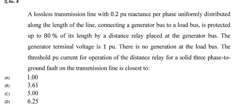
A lossless transmission line with 0.2 pu reactance per phase uniformly distributed along the length of the line, connecting a generator bus to a load bus, is protected up to 80 % of its length by a distance relay placed at the generator bus. The generator terminal voltage is 1 pu. There is no generation at the load bus. The threshold pu current for operation of the distance relay for a solid three phase-to-ground fault on the transmission line is closest to:

  1. (A)

    1.00

  2. (B)

    3.61

  3. (C)

    5.00

  4. (D)

    6.25

Answer and solution
See the question in the paper
GATE 2020 EE Q.8: answer and solution

PRACTICE

5 questions to test yourself

PRACTICE 12 marks · NAT

An IDMT relay with a very inverse characteristic, t = 13.5 x TMS / (PSM - 1), is connected to a 600/5 A CT. The plug setting is 150 % and the TMS is 0.2. For a primary fault current of 3600 A, find the operating time of the relay in seconds.

Answer and solution

Answer: (accepted range )

  1. CT ratio = 600/5 = 120. Secondary fault current = 3600/120 = 30 A.

  2. Pickup current = 1.5 x 5 = 7.5 A.

  3. PSM = 30/7.5 = 4.

  4. t = 13.5 x 0.2 / (4 - 1) = 2.7/3 = 0.9 s.

PRACTICE 21 mark · MCQ

A biased differential relay has a slope setting of 25 % (I_op must exceed 0.25 times the average through current; ignore any minimum pickup). During an external fault, the CT secondary currents at the two ends of the protected element are 5.0 A and 4.2 A, in phase. The relay will:

  1. (A)

    trip, because the difference current is non-zero

  2. (B)

    restrain, because the difference current (0.8 A) is below 0.25 x 4.6 A

  3. (C)

    trip, because the difference current exceeds 0.25 x 5.0 A

  4. (D)

    restrain, because the difference current is below 0.1 A

Answer and solution

Answer: (B)

  1. I_op = |5.0 - 4.2| = 0.8 A.

  2. I_r = (5.0 + 4.2)/2 = 4.6 A, so K I_r = 0.25 x 4.6 = 1.15 A.

  3. I_op = 0.8 A is less than 1.15 A, so the relay does not trip.

  4. Option B states exactly this.

PRACTICE 32 marks · MSQ

Which of the following statements about distance relays are correct?

  1. (A)

    A mho relay is inherently directional.

  2. (B)

    A plain impedance relay, with no added directional unit, is inherently directional.

  3. (C)

    A reactance relay measures only the reactive component of the apparent impedance, so in the ideal case fault arc resistance does not affect it.

  4. (D)

    Zone 1 of a step-distance scheme is normally set to 100 % of the protected line with a time delay.

Answer and solution

Answer: (A), (C)

  1. A is true: the mho circle passes through the origin and lies on one side of it.

  2. B is false: the impedance circle is centred on the origin, so the relay operates for faults in both directions.

  3. C is true: the reactance characteristic is a horizontal line in the R-X plane, so the relay depends only on X.

  4. D is false: Zone 1 is set short of the far end (about 80-90 %) and operates instantaneously.

PRACTICE 42 marks · NAT

A 220 kV line, 80 km long with a positive-sequence impedance of 0.5 ohm/km, is protected by a distance relay using a 1000/5 A CT and a 220 kV/110 V VT. Zone 1 is set at 80 % of the line. Find the Zone-1 reach in secondary ohms.

Answer and solution

Answer: (accepted range )

  1. Line impedance = 80 x 0.5 = 40 ohm. Zone 1 = 0.8 x 40 = 32 ohm (primary).

  2. N_CT = 1000/5 = 200. N_VT = 220000/110 = 2000.

  3. Z_sec = Z_pri x N_CT/N_VT = 32 x 200/2000 = 3.2 ohm.

PRACTICE 51 mark · MCQ

A three-phase circuit breaker is rated at 33 kV (line voltage) with a symmetrical rms breaking current of 20 kA. Its rated breaking capacity is nearest to:

  1. (A)

    660 MVA

  2. (B)

    1143 MVA

  3. (C)

    1980 MVA

  4. (D)

    2916 MVA

Answer and solution

Answer: (B)

  1. Breaking capacity = sqrt(3) x V_L x I_b.

  2. = 1.732 x 33 kV x 20 kA = 1143 MVA.

OFFICIAL GATE 2027 SYLLABUS WORDING

Copied from the GATE 2027 syllabus; see all 2027 syllabi.

GATE EE

Principles of over‐ current, differential, directional and distance protection; Circuit breakers

Preparing in Kolkata? IAE Academy's course for GATE EE.