IAE Academy

GATE EE

Dispatch & control

Economic dispatch, voltage and frequency control, power factor correction

This topic covers how real power is shared among generators at least cost, how frequency is held by governor action and supplementary control, and how voltage and reactive power are managed with taps, compensators and power factor correction. In GATE questions you will use the equal incremental cost condition, the penalty-factor form of it, the droop relation for load sharing, the area control error, and the tan-difference formula for the capacitor kVAr.

9 previous-year questions · 9 solved · 6 practice questions

Economic load dispatch without losses

Convention: the fuel cost of unit is in Rs/h with in MW, and a quadratic form is assumed unless stated. The incremental cost is the extra cost per hour for one more MW. The aim is to minimise the total cost while the generation equals the demand and each unit stays inside .

QUADRATIC COST AND INCREMENTAL COST

Cost in Rs/h, in MW; incremental cost is in Rs/MWh and is linear in .

EQUAL INCREMENTAL COST CRITERION (NO LOSSES)

A unit held at has ; a unit held at has . is the system incremental cost in Rs/MWh.

CLOSED FORM FOR QUADRATIC COSTS

Valid while every unit is inside its limits. The fixed term does not affect the dispatch.

Procedure with generator limits

  1. Solve the unconstrained problem using the closed form for .

  2. If a unit violates a limit, fix it at that limit.

  3. Subtract the fixed generation from and re-solve for the remaining units.

  4. Check that the remaining units are inside limits, and that each fixed unit satisfies its inequality on IC against the final .

WORKED EXAMPLE

Two units have and (Rs/h, MW). Find the economic dispatch for MW with no limits and no losses.

Solution
  1. , , so and .

  2. Sum: , so Rs/MWh.

  3. MW and MW.

  4. Check: and .

Answer: MW, MW, Rs/MWh.

EXAM TIP

Do not equalise the cost or the generation ; equalise the slopes. Inside limits, , so the unit with the smaller (the flatter IC line) takes the larger share of any change in load.

Economic dispatch with transmission losses

Power delivered to the load is generation minus the transmission loss . A unit whose extra output causes more loss is made to count for less. Convention: all and in MW and the loss coefficients in MW; the matrix is symmetric and treated as constant, and the simplest form has no or terms.

B-COEFFICIENT LOSS FORMULA

Symmetric . For two units: . is the incremental transmission loss of unit .

COORDINATION EQUATIONS

Holds for units inside limits. Here is the incremental cost of power delivered at the load.

PENALTY FACTOR FORM

Every unit inside limits has the same product of penalty factor and incremental cost. The approximation holds when is small. A unit with larger has a larger and so a lower optimal IC.

Iterative solution

  1. Guess (for example the lossless dispatch) and compute and each from the matrix.

  2. Compute the penalty factors .

  3. Solve together with for new .

  4. Repeat until the stop changing.

WORKED EXAMPLE

Two units have and (Rs/MWh, MW). The loss is MW (unit 1 is at the load). For Rs/MWh, find , , and the load .

Solution
  1. Unit 1: , so and , giving MW.

  2. Unit 2: . From the coordination equation, , so and MW.

  3. MW, so MW.

  4. Check: and .

Answer: MW, MW, MW, MW.

EXAM TIP

With losses the units do not run at equal incremental cost; they run at equal . If for all , every and the problem reduces to the lossless case.

Frequency control: governor droop and load sharing

Frequency falls when generation is less than load. The turbine governor senses speed and changes the valve opening. A governor with speed regulation (droop) lowers output as speed rises. Convention: is a per-unit number on the unit's own rating, with a negative sign understood, so 5% droop means and a 5% frequency change takes the unit from no load to full load. denotes a load increase in MW.

GOVERNOR DROOP

in per unit on the unit's own rating; is the change in generator output in steady state with the speed changer setting fixed.

LOAD SHARING OF PARALLEL UNITS

All units settle at one common frequency. A smaller or a larger rating takes a larger share of a load change, as long as no unit reaches its limit.

STEADY-STATE FREQUENCY CHANGE FOR A LOAD CHANGE

Free governor action, no supplementary control. is the load increase in MW and is load damping in MW/Hz (set if not given).

WORKED EXAMPLE

Two units share a 50 Hz system: 100 MW with and 200 MW with , both on their own ratings. A load increase of 30 MW occurs. Neglect load damping; both units have spare capacity. Find the new frequency and each unit's share.

Solution
  1. MW per unit of .

  2. , so Hz.

  3. Unit 1: MW. Unit 2: MW.

  4. Check: MW.

Answer: Hz; unit 1 takes 11.54 MW and unit 2 takes 18.46 MW.

EXAM TIP

Droop percentages are on each unit's own MW rating. Convert to a common base, or use as above, before combining units of different size.

Load-frequency control basics and area control error

Governor droop alone leaves a steady frequency error. Load-frequency control (LFC) adds a supplementary integral loop that moves the speed changer setting of selected units until the error is removed. In an interconnected system each area also has to hold its scheduled exchange on the tie line. Convention in this section: in Hz/MW, so ; in MW/Hz; tie-line flow positive out of the area.

AREA FREQUENCY RESPONSE CHARACTERISTIC

For one isolated area with governor action only (no integral control). is the governor response of unit and the load damping.

TWO AREAS, GOVERNOR ACTION ONLY

Steady state with no supplementary control; is the change in flow from area 1 to area 2. For a load step in area 1 only, : area 2 sends part of the step over the tie line.

TIE-LINE POWER AND SYNCHRONISING COEFFICIENT

Lossless tie line of reactance , small deviations about the operating angle ; per phase or per unit consistently.

AREA CONTROL ERROR

is the tie-line flow deviation (positive out of the area) and is the frequency bias in MW/Hz, commonly set equal to the area's . The integral controller changes the set point as : negative ACE raises generation.

What the supplementary integral loop achieves

  1. Condition: each area has integral control acting on its own ACE.

  2. In steady state the integral controllers make . Since , this forces and .

  3. So after a load step in one area the frequency returns to its scheduled value and the tie-line flow returns to its schedule: the area that had the load change supplies it from its own units.

  4. Primary control (droop) acts first; supplementary control (LFC) is slower and removes the remaining error.

EXAM TIP

Watch the signs. After a load rise in area 1, area 1 has and (it draws extra power in), so both ACE terms are negative and its units raise generation. Area 2 has but ; with the two terms cancel at the governor-only steady state, so area 2 does not change its setting.

Voltage control and reactive power

In a mainly inductive network, bus voltage is tied to reactive power: drawing lagging reactive power lowers the bus voltage and supplying it raises the voltage. Voltage is controlled locally by tap changers, shunt and series compensation and generator excitation, while real power and frequency are system-wide quantities.

APPROXIMATE VOLTAGE DROP ON A LINE

Per phase or per unit consistently; and are the real and lagging reactive power received, the receiving-end voltage; valid for a small angle across the line. In a mainly inductive line () the drop depends mostly on .

VOLTAGE RISE FROM REACTIVE INJECTION

Reactive power injected (for example by a shunt capacitor) at a bus whose Thevenin source reactance is ; is the three-phase short-circuit level at that bus (per-unit form, dominant).

OFF-NOMINAL TAP SETTING FOR A LINE

Tap-changing transformers at both ends of a line of impedance . and are the nominal voltages at the two ends referred to the line side, and are the power received at end 2, and the angle across the line is small. With : .

Methods of voltage control

Method

How it acts

Remark

Tap-changing transformer

Changes the turns ratio, shifting the secondary voltage by steps

Generates no reactive power; it only redistributes the reactive flow

Shunt capacitor

Supplies reactive power (draws leading current)

Raises voltage; its output varies as , so it falls when voltage is low

Shunt reactor

Absorbs reactive power

Lowers voltage at light load or on long lines

Series capacitor

Cancels part of the line's series reactance

Voltage rise grows with load current, so it adjusts itself to the load

Synchronous condenser

Over-excited it supplies , under-excited it absorbs

Continuously variable reactive output

Generator excitation (AVR)

Changes the generator's reactive output

Over-excitation supplies , under-excitation absorbs

SVC / STATCOM

Power-electronic control of reactive power

Fast, continuously variable supply or absorption of

EXAM TIP

A tap changer supplies no reactive power. Raising the load-side voltage with a tap makes the load draw more reactive power through the transformer, which lowers the supply-side voltage. When the system is short of , this can make the upstream voltage worse.

Power factor correction with shunt capacitors

A shunt capacitor at the load supplies part of the lagging reactive power the load needs, so the source supplies less. The load's own real power and reactive demand do not change, and the load voltage is taken as constant (the small voltage rise from the capacitor is neglected). Convention: lagging power factor, lagging positive, before and after correction.

CAPACITOR RATING

Total three-phase kVAr for total real power in kW. The rating is the reactive power the bank delivers at its rated voltage.

CAPACITANCE FROM THE KVAR RATING

is the three-phase VAr, the line voltage in V, , and comes out in F. Note .

EFFECT ON LINE CURRENT AND LOSS

At constant and constant load voltage, the source-side current falls when , and feeder loss falls with its square.

MOST ECONOMICAL POWER FACTOR

Constant ; demand charge per kVA of maximum demand per year and capacitor annual cost per kVAr per year (both linear). It minimises .

WORKED EXAMPLE

A three-phase load takes 400 kW at 0.8 lagging. Find the capacitor kVAr needed to raise the power factor to 0.95 lagging, and the new apparent power.

Solution
  1. , so kVAr.

  2. , so and kVAr.

  3. kVAr.

  4. New apparent power kVA (down from kVA).

Answer: kVAr; kVA.

EXAM TIP

Use the tan difference, not a difference of angles or of power factors. Correcting past unity pf makes the load leading, and then the line current rises again.

PREVIOUS-YEAR QUESTIONS

9 questions from the EE papers

Try each question first, then open the answer. We placed each question under a topic ourselves; the exam paper does not label topics.

See these papers in full: GATE EE 2026 · GATE EE 2025 · GATE EE 2024 · GATE EE 2023 · GATE EE 2022 · GATE EE 2020

GATE 2026 EE Q.58

GATE 2026 · EEQ.58 · 2 marks · NAT

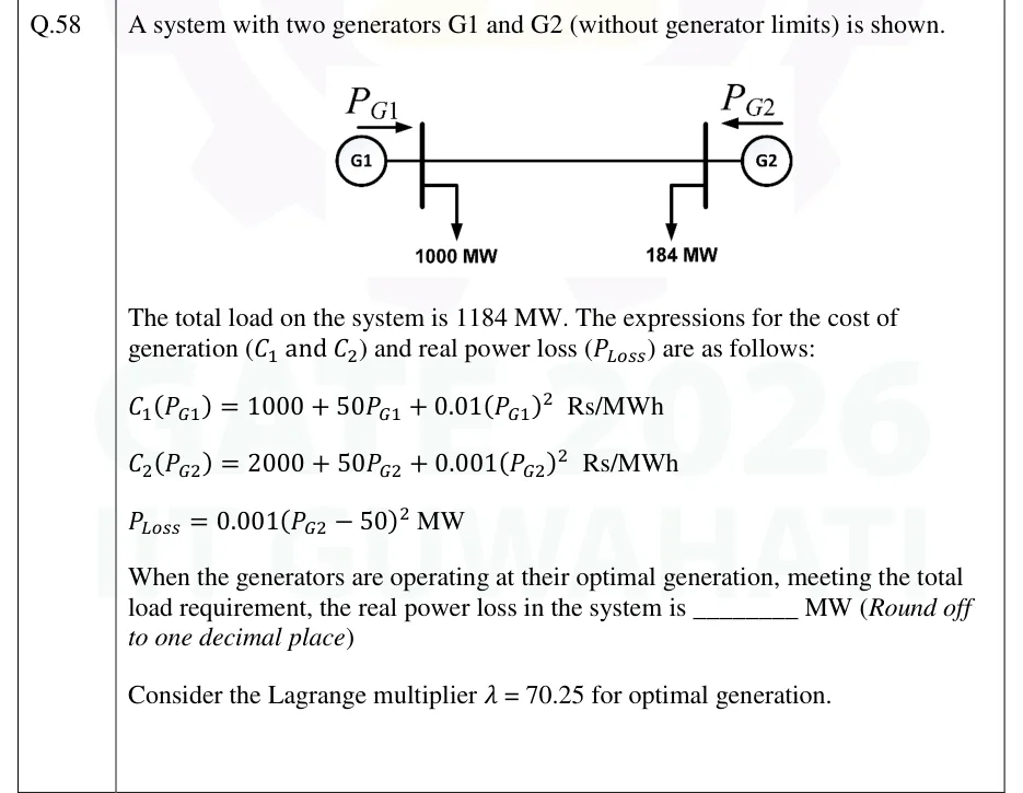
A system with two generators G1 and G2 (without generator limits) is shown. The total load on the system is 1184 MW. The expressions for the cost of generation (C_1 and C_2) and real power loss (P_Loss) are as follows: C_1(P_G1) = 1000 + 50 P_G1 + 0.01 (P_G1)^2 Rs/MWh; C_2(P_G2) = 2000 + 50 P_G2 + 0.001 (P_G2)^2 Rs/MWh; P_Loss = 0.001 (P_G2 - 50)^2 MW. When the generators are operating at their optimal generation, meeting the total load requirement, the real power loss in the system is ________ MW (Round off to one decimal place). Consider the Lagrange multiplier lambda = 70.25 for optimal generation.
GATE 2026 EE question 58: Single-line diagram: generator G1 on the left feeds a bus with power P_G1 flowing in (arrow to the right) and a load of…Tap to open full size
Figure from the GATE 2026 EE paper. It is part of the question.
Figure description

Single-line diagram: generator G1 on the left feeds a bus with power P_G1 flowing in (arrow to the right) and a load of 1000 MW tapped from that bus; a line joins it to a right bus where generator G2 supplies P_G2 (arrow to the left) and a load of 184 MW is tapped. Loads total 1184 MW.

Answer and solution
GATE 2026 EE Q.58: answer and solution

GATE 2025 EE Q.64

GATE 2025 · EEQ.64 · 2 marks · NAT

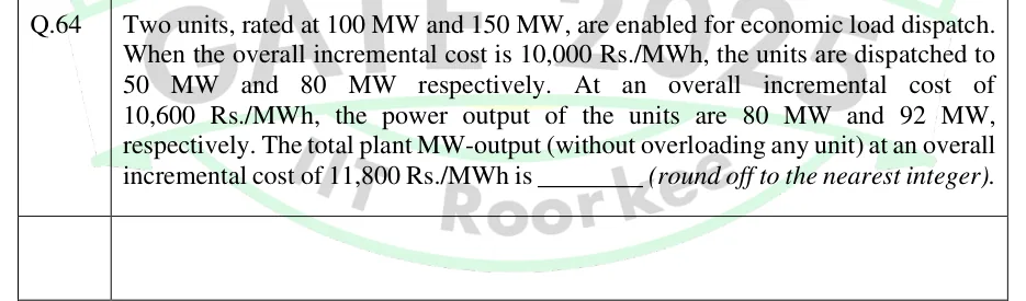
Two units, rated at 100 MW and 150 MW, are enabled for economic load dispatch. When the overall incremental cost is 10,000 Rs./MWh, the units are dispatched to 50 MW and 80 MW respectively. At an overall incremental cost of 10,600 Rs./MWh, the power output of the units are 80 MW and 92 MW, respectively. The total plant MW-output (without overloading any unit) at an overall incremental cost of 11,800 Rs./MWh is ________ (round off to the nearest integer).

Answer and solution
See the question in the paper
GATE 2025 EE Q.64: answer and solution

GATE 2024 EE Q.34

GATE 2024 · EEQ.34 · 1 mark · NAT

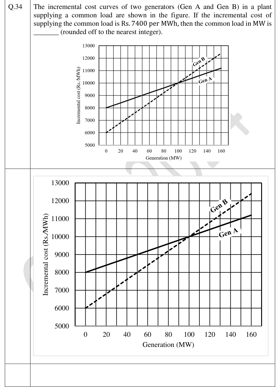
The incremental cost curves of two generators (Gen A and Gen B) in a plant supplying a common load are shown in the figure. If the incremental cost of supplying the common load is Rs. 7400 per MWh, then the common load in MW is ______ (rounded off to the nearest integer).

GATE 2024 EE question 34: Graph of incremental cost (Rs./MWh, vertical axis, 5000 to 13000 in steps of 1000) against generation (MW, horizontal…Tap to open full size
Figure from the GATE 2024 EE paper. It is part of the question.
Figure description

Graph of incremental cost (Rs./MWh, vertical axis, 5000 to 13000 in steps of 1000) against generation (MW, horizontal axis, 0 to 160 in steps of 20). Gen A is a solid straight line starting at (0 MW, 8000), passing through (50, 9000) and (100, 10000), ending near (160, 11200). Gen B is a dashed straight line starting at (0, 6000), passing through (50, 8000) and (100, 10000), ending near (160, 12400). The two lines intersect at (100 MW, 10000).

Answer and solution
GATE 2024 EE Q.34: answer and solution

GATE 2024 EE Q.47

GATE 2024 · EEQ.47 · 2 marks · MSQ

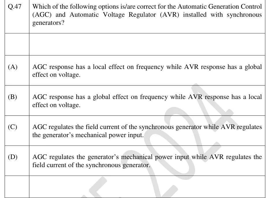
Which of the following options is/are correct for the Automatic Generation Control (AGC) and Automatic Voltage Regulator (AVR) installed with synchronous generators?

  1. (A)

    AGC response has a local effect on frequency while AVR response has a global effect on voltage.

  2. (B)

    AGC response has a global effect on frequency while AVR response has a local effect on voltage.

  3. (C)

    AGC regulates the field current of the synchronous generator while AVR regulates the generator's mechanical power input.

  4. (D)

    AGC regulates the generator's mechanical power input while AVR regulates the field current of the synchronous generator.

Answer and solution
See the question in the paper
GATE 2024 EE Q.47: answer and solution

GATE 2023 EE Q.21

GATE 2023 · EEQ.21 · 1 mark · MCQ

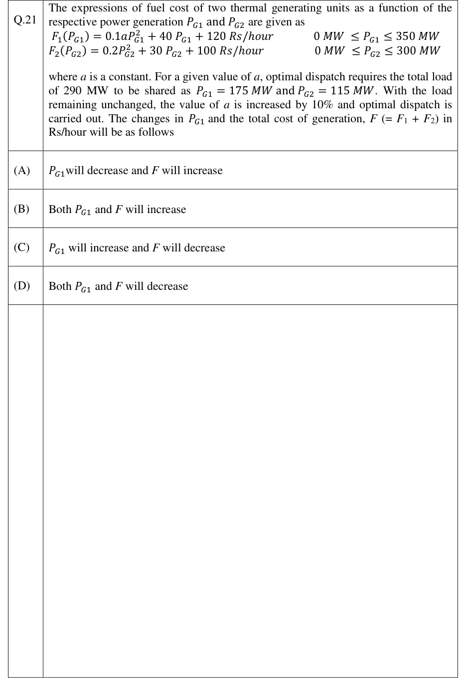
The expressions of fuel cost of two thermal generating units as a function of the respective power generation P_G1 and P_G2 are given as
F_1(P_G1) = 0.1 a P_G1^2 + 40 P_G1 + 120 Rs/hour, 0 MW ≤ P_G1 ≤ 350 MW
F_2(P_G2) = 0.2 P_G2^2 + 30 P_G2 + 100 Rs/hour, 0 MW ≤ P_G2 ≤ 300 MW
where a is a constant. For a given value of a, optimal dispatch requires the total load of 290 MW to be shared as P_G1 = 175 MW and P_G2 = 115 MW. With the load remaining unchanged, the value of a is increased by 10% and optimal dispatch is carried out. The changes in P_G1 and the total cost of generation, F (= F_1 + F_2) in Rs/hour will be as follows

  1. (A)

    P_G1 will decrease and F will increase

  2. (B)

    Both P_G1 and F will increase

  3. (C)

    P_G1 will increase and F will decrease

  4. (D)

    Both P_G1 and F will decrease

Answer and solution
See the question in the paper
GATE 2023 EE Q.21: answer and solution

GATE 2022 EE Q.43

GATE 2022 · EEQ.43 · 2 marks · MCQ

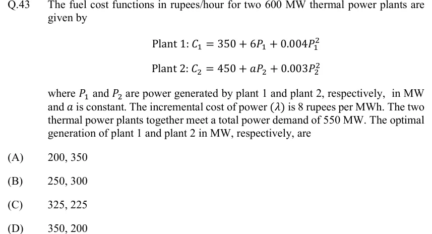
The fuel cost functions in rupees/hour for two 600 MW thermal power plants are given by Plant 1: ; Plant 2: , where and are power generated by plant 1 and plant 2, respectively, in MW and is constant. The incremental cost of power () is 8 rupees per MWh. The two thermal power plants together meet a total power demand of 550 MW. The optimal generation of plant 1 and plant 2 in MW, respectively, are

  1. (A)

    200, 350

  2. (B)

    250, 300

  3. (C)

    325, 225

  4. (D)

    350, 200

Answer and solution
See the question in the paper
GATE 2022 EE Q.43: answer and solution

GATE 2022 EE Q.56

GATE 2022 · EEQ.56 · 2 marks · NAT

Two generating units rated for 250 MW and 400 MW have governor speed regulations of 6% and 6.4%, respectively, from no load to full load. Both the generating units are operating in parallel to share a load of 500 MW. Assuming free governor action, the load shared in MW, by the 250 MW generating unit is __________. (round off to nearest integer)

Answer and solution
See the question in the paper
GATE 2022 EE Q.56: answer and solution

GATE 2020 EE Q.23

GATE 2020 · EEQ.23 · 1 mark · NAT

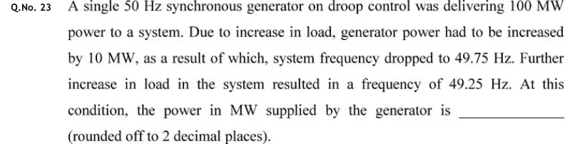
A single 50 Hz synchronous generator on droop control was delivering 100 MW power to a system. Due to increase in load, generator power had to be increased by 10 MW, as a result of which, system frequency dropped to 49.75 Hz. Further increase in load in the system resulted in a frequency of 49.25 Hz. At this condition, the power in MW supplied by the generator is ______ (rounded off to 2 decimal places).

Answer and solution
See the question in the paper
GATE 2020 EE Q.23: answer and solution

PRACTICE

6 questions to test yourself

PRACTICE 12 marks · NAT

Two units have incremental costs and (Rs/MWh, in MW). Neglect losses and limits. For a total demand of 250 MW, the economic output of unit 1 in MW is ____.

Answer and solution

Answer: (accepted range )

  1. Equal IC: with .

  2. , so .

  3. MW; then MW and both ICs equal 15.2 Rs/MWh.

PRACTICE 22 marks · NAT

A 415 V, 50 Hz, three-phase load takes 100 kW at 0.8 power factor lagging. A delta-connected capacitor bank raises the power factor to 0.95 lagging. The capacitance required per phase, in F, is ____ (round to one decimal place).

Answer and solution

Answer: (accepted range )

  1. kVAr.

  2. Delta: .

  3. F F.

PRACTICE 31 mark · MCQ

Two identical 100 MW generators run in parallel at the same no-load frequency. Their governor speed regulations are 4% and 6% on their own ratings. With a common load of 100 MW in total and free governor action, the shares of unit 1 and unit 2 are respectively

  1. (A)

    50 MW and 50 MW

  2. (B)

    60 MW and 40 MW

  3. (C)

    40 MW and 60 MW

  4. (D)

    66.7 MW and 33.3 MW

Answer and solution

Answer: (B)

  1. Share is proportional to , which is and for equal ratings.

  2. Unit 1 fraction: .

  3. So 60 MW and 40 MW.

PRACTICE 41 mark · NAT

A load draws constant real power at constant voltage through a feeder of fixed resistance. A shunt capacitor at the load improves its power factor from 0.8 lagging to unity. The feeder loss after correction, as a fraction of the loss before correction, is ____ (round to two decimal places).

Answer and solution

Answer: (accepted range )

  1. At constant and , .

  2. .

  3. Loss ratio .

PRACTICE 51 mark · NAT

The transmission loss of a system is MW, with in MW. When unit 1 generates 500 MW, its penalty factor is ____ (round to two decimal places).

Answer and solution

Answer: (accepted range )

  1. .

  2. .

PRACTICE 62 marks · MSQ

Which of the following statements are correct? (Losses described by .)

  1. (A)

    The penalty factor of unit is .

  2. (B)

    For units inside their limits the optimum has equal for all units.

  3. (C)

    In the lossless problem, a unit held at its upper limit must have incremental cost equal to .

  4. (D)

    For two parallel units of equal rating under free governor action, the unit with the smaller speed regulation takes the larger share of a load change.

Answer and solution

Answer: (A), (B), (D)

  1. A is the definition of the penalty factor.

  2. B is the coordination equation written with penalty factors.

  3. C is false: a unit at its upper limit has ; it is not required to equal .

  4. D is true because the share is proportional to .

OFFICIAL GATE 2027 SYLLABUS WORDING

Copied from the GATE 2027 syllabus; see all 2027 syllabi.

GATE EE

Economic Load Dispatch (with and without considering transmission losses) … Voltage and Frequency control, Power factor correction

Preparing in Kolkata? IAE Academy's course for GATE EE.