IAE Academy

GATE EE

Symmetrical components and fault analysis

Symmetrical components resolve any unbalanced three-phase set into three balanced sets (positive, negative and zero sequence), so an unsymmetrical fault becomes an interconnection of three single-phase sequence networks. Fault MVA and the symmetrical and unsymmetrical fault currents all follow from the sequence impedances at the fault bus. These notes cover the network connection for each fault, the effect of fault and neutral impedance, the zero-sequence path through transformers, the DC offset of a short circuit and fault studies with the bus impedance matrix.

8 previous-year questions · 7 solved · 5 practice questions

Symmetrical components and the a-operator

Convention used throughout: per-unit values on stated MVA and kV bases, phasors written with magnitude and angle, is the imaginary unit, , and quantities are per phase unless stated. Phase is the reference phase. The three sequence networks are named positive (1), negative (2) and zero (0).

Any unbalanced set of three phasors equals the sum of three sets. The positive-sequence set has equal magnitudes, displaced in the order --. The negative-sequence set has equal magnitudes in the order --. The zero-sequence set has three equal phasors in phase with each other.

THE A-OPERATOR

Multiplying a phasor by rotates it by anticlockwise without changing its magnitude. Also .

SYNTHESIS (PHASE FROM SEQUENCE)

Same form for currents. Here and .

ANALYSIS (SEQUENCE FROM PHASE)

Same form for currents. The inverse matrix is times the complex conjugate of the synthesis matrix.

NEUTRAL CURRENT

Only the zero-sequence component flows in the neutral (or earth) return path. If there is no neutral path, in the line currents. So the line currents of a three-wire system (delta or ungrounded star) contain no zero-sequence component, although zero-sequence current can still circulate inside a delta winding.

THREE-PHASE COMPLEX POWER IN SEQUENCE COMPONENTS

The factor 3 appears because the transformation used here (with in the analysis equations) is not power-invariant. There are no cross terms between different sequences.

Facts worth remembering

  1. A balanced set in the phase order -- has only a positive-sequence component; a balanced set in the order -- has only a negative-sequence component.

  2. Line voltages carry no zero-sequence component, because .

  3. The sequence components of phases and differ from those of only by factors of and , so one phase carries all the information.

  4. With phase as reference, is the positive-sequence voltage of phase , the positive-sequence voltage of phase is and the negative-sequence voltage of phase is .

Sequence impedances and sequence networks

The impedance an element presents to a set of currents depends on the sequence. For static, balanced elements (transposed lines, transformers) reversing the phase order does not change the mutual coupling, so positive and negative sequence impedances are equal. Rotating machines respond differently to the forward and backward rotating fields, so in general.

Element

Positive

Negative

Zero

Transmission line (transposed)

Series impedance per phase

Larger than , because zero-sequence current returns through earth and any ground wires

Transformer

Leakage impedance

Equal to the leakage impedance for a bank of single-phase units, approximately equal for three-phase units; how it connects into the network depends on the winding connection and grounding

Synchronous generator

Sub-transient, transient or synchronous reactance, as the study requires

Different from ; close to the sub-transient reactance

Small, set by winding leakage; the network value is if grounded through , and an open circuit if the neutral is ungrounded

Induction motor (as a source in the first cycles)

Sub-transient reactance

Close to

No zero-sequence path if the stator is delta or ungrounded star

SEQUENCE NETWORK EQUATIONS AT THE FAULT BUS

For a system that is balanced before the fault, with balanced sources, only the positive-sequence network has a source: , the pre-fault voltage of the reference phase at the fault bus. The negative and zero networks are passive. are the Thevenin impedances seen from the fault point, and are the sequence currents flowing out of the system into the fault.

NEUTRAL IMPEDANCE IN THE ZERO-SEQUENCE NETWORK

A neutral impedance carries , so it appears as in the single-phase zero-sequence network. It does not appear in the positive or negative networks.

Transformer connection (HV - LV)

Zero-sequence representation

Yg - Yg (both neutrals solidly grounded)

Leakage impedance connects the two buses; zero-sequence current passes through

Yg - Yg grounded through (HV) and (LV)

Leakage impedance between the buses, with and in series

Yg -

Leakage impedance from the Yg-side bus to reference; the delta-side bus is not connected to the Yg side (current circulates inside the delta)

Y (ungrounded) - any

Open circuit on the ungrounded side, so no zero-sequence path through the transformer

-

Open circuit; no path to reference on either side

Yg through -

As for Yg - , with added in series with the leakage impedance on the Yg side

EXAM TIP

A transformer winding gives zero-sequence current a path on its own side when it is star-connected with its neutral grounded. A delta or ungrounded-star winding gives no zero-sequence path into its own side's network. A delta winding opposite a grounded star lets the current circulate but keeps it out of the delta-side network. A star-delta bank shifts the positive and negative sequences in opposite directions: if positive-sequence quantities shift by from one side to the other, negative-sequence quantities shift by . Zero sequence is not shifted. The shift does not change the current at the fault point. It must be applied when finding phase currents or voltages on the other side of the transformer, because the positive and negative components then recombine at different angles.

Symmetrical three-phase fault and fault MVA

A balanced three-phase fault involves only the positive-sequence network, because the system stays balanced. Take the pre-fault voltage at the fault bus as (1 pu if not given) and neglect pre-fault load current unless the question includes it.

THREE-PHASE FAULT CURRENT (PER UNIT)

is the positive-sequence Thevenin impedance at the fault bus, the impedance in each phase of the fault. For a bolted fault .

BASE CURRENT

in VA for the three-phase rating and the line-to-line voltage in volts, giving in amperes.

FAULT MVA (SHORT-CIRCUIT CAPACITY)

For a bolted three-phase fault with pu. In per unit it equals . is in MVA, is the base (rated) line-to-line voltage in volts and is the fault current in amperes.

CHANGE OF BASE

Convert every element to the common MVA base, and to the common voltage base in each voltage zone, before combining.

Machine reactance

Meaning

Where it is used

Sub-transient

Smallest; the effective reactance in the first few cycles

Initial symmetrical short-circuit current, momentary current

Transient

Larger; applies after the sub-transient effect decays

Current in the transient period, a few cycles after the fault

Synchronous

Largest; the steady-state value

Steady-state fault current after all decay

EXAM TIP

If a question gives all three reactances, read the wording to see which instant is needed: 'initial' or 'sub-transient' means , 'steady state' means . A larger reactance gives a smaller current, so the sub-transient reactance gives the largest of the three currents.

SHORT CIRCUIT OF A SERIES R-L CIRCUIT (DC OFFSET)

A voltage drives a series - circuit that carries no current at . The angle sets the instant of the fault on the voltage wave. There is no DC offset when . The DC offset is largest when . Then, if is small compared with , the first current peak approaches , twice the steady-state peak. This model takes a constant reactance and ignores the machine's change from sub-transient to synchronous reactance.

Pre-fault load current. With load, the pre-fault voltage at the fault bus is not exactly 1 pu. By Thevenin's theorem, the current into the fault is , using the actual pre-fault voltage. The current in each branch (a generator or line, say) after the fault is its pre-fault load current plus the change caused by the fault, found from the Thevenin circuit. When the question says to neglect load current, use pu at no load.

Unsymmetrical faults

Each fault is placed symmetrically about the reference phase : the SLG fault on phase , and the LL and DLG faults on phases and . The system is balanced before the fault and pre-fault load current is neglected, so is the pre-fault (Thevenin) voltage of phase at the fault bus. are the Thevenin sequence impedances at that bus and is the fault impedance. The sequence networks are then connected as below.

Fault

Phases

Network connection

Zero-sequence current?

Single line-to-ground (SLG)

to ground through

All three networks in series, with added

Yes

Line-to-line (LL)

to through

Positive and negative networks connected terminal to terminal, with in series between them; zero network unused

No

Double line-to-ground (DLG)

and to ground through

Positive network in series with the parallel combination of the negative network and (zero network + )

Yes

Three-phase

, , shorted together

Positive network only

No

SINGLE LINE-TO-GROUND FAULT (PHASE A)

Fault conditions: and . The fault current through the ground is .

LINE-TO-LINE FAULT (PHASES B AND C)

is the impedance connected between and . and . No current flows to ground.

DOUBLE LINE-TO-GROUND FAULT (PHASES B AND C TO GROUND)

is the impedance in the common earth path of both phases. and the current into the ground is .

CHECK FOR LL AND DLG FAULTS

Phase is healthy in these faults, so its sequence currents add to zero. Use it to check an answer.

WORKED EXAMPLE

A synchronous generator rated 20 MVA, 11 kV has , and pu on its own rating, with a solidly grounded neutral. It is on no load at 1 pu voltage when a bolted single line-to-ground fault occurs on phase at its terminals. Find the fault current in per unit and in amperes.

Solution
  1. Since and the neutral is solidly grounded: pu.

  2. Fault current , so pu.

  3. Base current: A.

  4. A.

Answer: 6.0 pu, about 6300 A

WORKED EXAMPLE

For the same generator and the same terminal location, find the fault current magnitude for a bolted line-to-line fault between phases and , and the ground current for a bolted double line-to-ground fault. Compare with the three-phase fault current.

Solution
  1. Three-phase: pu, about A.

  2. LL: pu, so pu, about 4545 A. With the LL current is times the three-phase current.

  3. DLG: pu, so pu.

  4. pu, so the ground current is pu, about 7873 A.

  5. The SLG current exceeds the three-phase current only when . Here and , so the SLG current (6.0 pu) exceeds the three-phase current (5.0 pu). This does not hold for every system.

Answer: LL: 4.33 pu (about 4545 A). DLG ground current: 7.5 pu (about 7873 A). Three-phase: 5.0 pu (about 5249 A).

Effect of fault and neutral impedance; bus impedance matrix

How impedances enter the sequence networks

  1. Fault impedance in an SLG fault: add in series in the connection of the three networks.

  2. Fault impedance between phases in an LL fault: add in series in the loop of the positive and negative networks.

  3. Fault impedance in the earth path of a DLG fault: add in series with .

  4. Neutral impedance of a generator or transformer: add to that element's zero-sequence impedance.

  5. If the only ground source is a star point grounded through a very large impedance, or not grounded at all, is very large and the ground-fault current is very small.

The bus impedance matrix of each sequence network gives the Thevenin impedance at every bus at once. For a fault at bus , the diagonal element of that sequence's matrix is the Thevenin impedance at bus . The off-diagonal element is the voltage at bus per unit of current injected at bus . The matrix is either given or built by adding branches one at a time.

THREE-PHASE FAULT USING Z_BUS

is the pre-fault voltage at bus , the post-fault voltage at bus , and the positive-sequence matrix.

SEQUENCE VOLTAGES AT BUS I FOR AN UNSYMMETRICAL FAULT AT BUS K

Find the sequence fault currents from the formulas of the previous section with , , and . Each sequence voltage is updated with its own matrix, then combined into phase voltages with the synthesis matrix. If a star-delta transformer lies between buses and , shift the positive and negative sequence values by its phase shift before combining.

Building Z_bus by adding a branch of impedance $Z_b$

  1. New branch from a new bus to the reference: the new diagonal element is , and all new off-diagonal elements are zero.

  2. New branch from a new bus to an existing bus : for every existing bus , and .

  3. A branch from an existing bus to the reference, or between two existing buses, modifies every element of the matrix, by the formulas below (the size of the matrix does not change).

ADDING A BRANCH TO EXISTING BUSES (KRON REDUCTION)

Apply to every element of the existing matrix. Both results come from adding a temporary extra row and column and eliminating it.

EXAM TIP

Check the size of any answer. With a large , the SLG fault current falls well below the three-phase fault current. A solidly grounded system with small can give an SLG current above the three-phase value. Drawing the sequence-network connection first, with every terminal labelled, prevents most sign and connection mistakes.

PREVIOUS-YEAR QUESTIONS

8 questions from the EE papers

Try each question first, then open the answer. We placed each question under a topic ourselves; the exam paper does not label topics.

See these papers in full: GATE EE 2026 · GATE EE 2025 · GATE EE 2024 · GATE EE 2023 · GATE EE 2022 · GATE EE 2018

GATE 2026 EE Q.19

GATE 2026 · EEQ.19 · 1 mark · MCQ

The initial three-phase voltage phasors (V_A, V_B and V_C) at a bus of a power network are as shown in Case-1. Due to a disturbance, the bus voltage phasors changed in phase by a small angle Δθ, and the magnitudes remained the same as depicted in Case-2.

Which one of the following statements is correct about the zero sequence components?
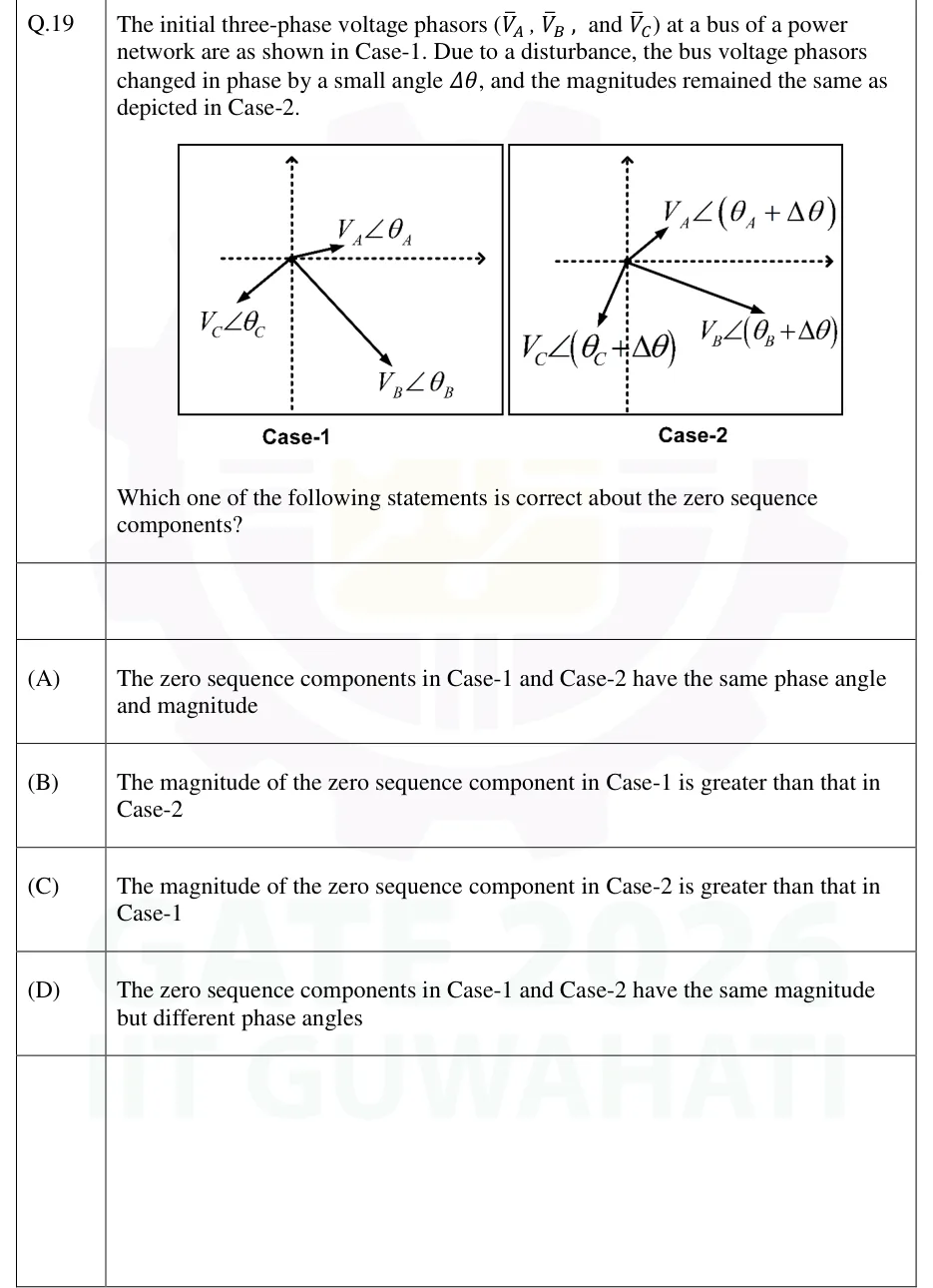
GATE 2026 EE question 19: Two boxed phasor diagrams, Case-1 and Case-2, each with a horizontal dashed real axis and a vertical dashed imaginary axis…Tap to open full size
Figure from the GATE 2026 EE paper. It is part of the question.
Figure description

Two boxed phasor diagrams, Case-1 and Case-2, each with a horizontal dashed real axis and a vertical dashed imaginary axis through the origin. Case-1: V_A at angle θ_A points up and to the right (shortest arrow, upper right); V_B at angle θ_B points down and to the right (longest arrow, lower right); V_C at angle θ_C points down and to the left (lower left). Case-2: the same three phasors with the same lengths, each rotated by the same small angle Δθ: V_A at angle (θ_A + Δθ) in the upper right, V_B at (θ_B + Δθ) in the lower right (rotated anticlockwise, so flatter), V_C at (θ_C + Δθ) in the lower left (rotated anticlockwise, so steeper). Magnitudes V_A, V_B, V_C are unchanged.

  1. (A)

    The zero sequence components in Case-1 and Case-2 have the same phase angle and magnitude

  2. (B)

    The magnitude of the zero sequence component in Case-1 is greater than that in Case-2

  3. (C)

    The magnitude of the zero sequence component in Case-2 is greater than that in Case-1

  4. (D)

    The zero sequence components in Case-1 and Case-2 have the same magnitude but different phase angles
Answer and solution
GATE 2026 EE Q.19: answer and solution

GATE 2025 EE Q.33

GATE 2025 · EEQ.33 · 1 mark · NAT

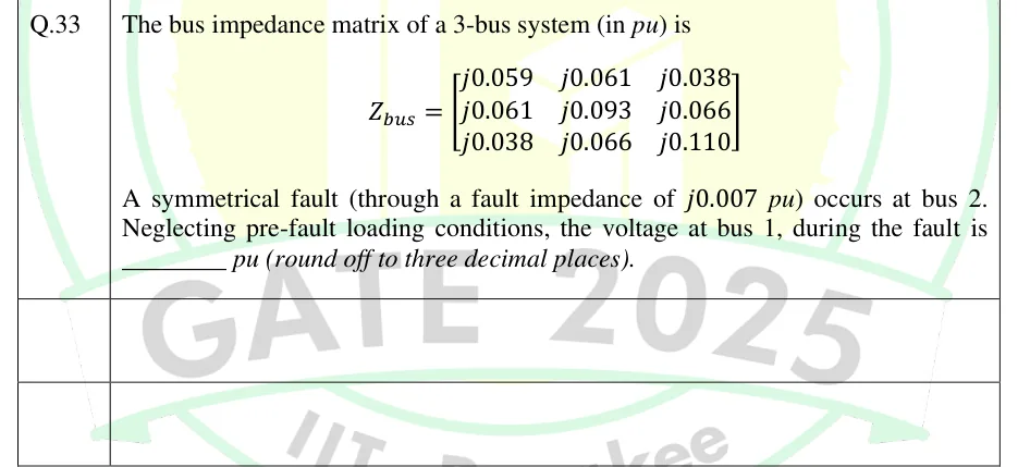
The bus impedance matrix of a 3-bus system (in pu) is Z_bus = [[j0.059, j0.061, j0.038],[j0.061, j0.093, j0.066],[j0.038, j0.066, j0.110]]. A symmetrical fault (through a fault impedance of j0.007 pu) occurs at bus 2. Neglecting pre-fault loading conditions, the voltage at bus 1, during the fault is ________ pu (round off to three decimal places).

Answer and solution
See the question in the paper
GATE 2025 EE Q.33: answer and solution

GATE 2024 EE Q.46

GATE 2024 · EEQ.46 · 2 marks · MSQ

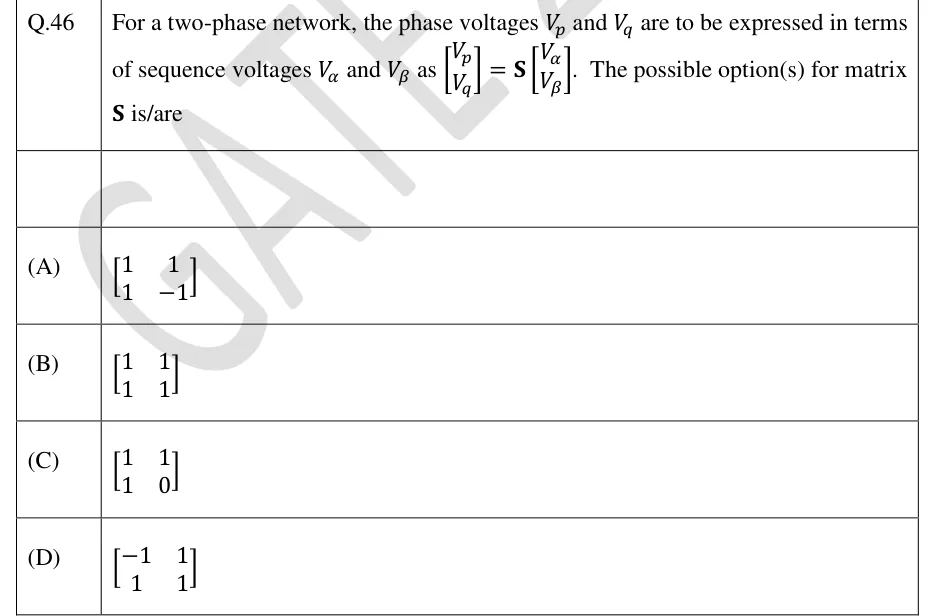
For a two-phase network, the phase voltages and are to be expressed in terms of sequence voltages and as . The possible option(s) for matrix is/are

  1. (A)

  2. (B)

  3. (C)

  4. (D)

Official answer
See the question in the paper
GATE 2024 EE Q.46: official answer

GATE 2023 EE Q.60

GATE 2023 · EEQ.60 · 2 marks · NAT

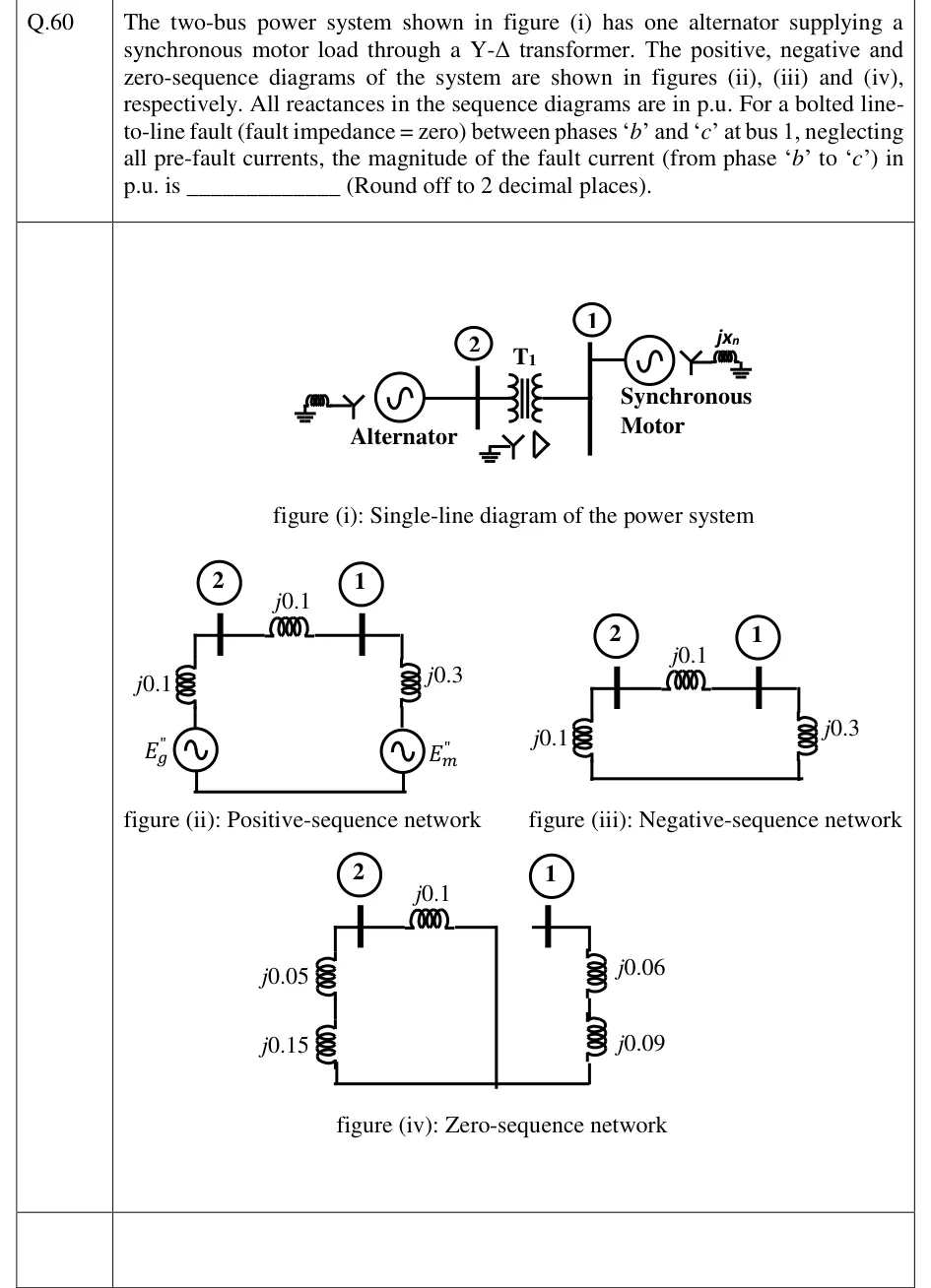
The two-bus power system shown in figure (i) has one alternator supplying a synchronous motor load through a Y-Δ transformer. The positive, negative and zero-sequence diagrams of the system are shown in figures (ii), (iii) and (iv), respectively. All reactances in the sequence diagrams are in p.u. For a bolted line-to-line fault (fault impedance = zero) between phases 'b' and 'c' at bus 1, neglecting all pre-fault currents, the magnitude of the fault current (from phase 'b' to 'c') in p.u. is ____________ (Round off to 2 decimal places).

GATE 2023 EE question 60: Figure (i): single-line diagram.Tap to open full size
Figure from the GATE 2023 EE paper. It is part of the question.
Figure description

Figure (i): single-line diagram. A grounded-Y alternator (with a reactor to ground) connects to bus 2; transformer T1 (grounded-Y on the bus 2 side, delta on the bus 1 side) connects bus 2 to bus 1; at bus 1 a synchronous motor (Y, grounded through reactance jXn) is connected. Figure (ii) positive sequence: Eg'' source in series with j0.1 up to bus 2; j0.1 between bus 2 and bus 1; at bus 1 a j0.3 reactance in series with the source Em'' returning to the reference. Figure (iii) negative sequence: same as (ii) but with no sources: j0.1 from bus 2 to reference, j0.1 between bus 2 and bus 1, j0.3 from bus 1 to reference. Figure (iv) zero sequence: at bus 2, j0.05 and j0.15 in series to reference; j0.1 between bus 2 and the transformer's zero-sequence break (the delta side is isolated from the line); at bus 1, j0.06 and j0.09 in series to reference, with no connection between the two sides.

Answer and solution
GATE 2023 EE Q.60: answer and solution

GATE 2018 EE Q.20

GATE 2018 · EEQ.20 · 1 mark · NAT

The series impedance matrix of a short three-phase transmission line in phase coordinates is [[Z_s, Z_m, Z_m],[Z_m, Z_s, Z_m],[Z_m, Z_m, Z_s]]. If the positive sequence impedance is (1 + j10) Ω, and the zero sequence is (4 + j31) Ω, then the imaginary part of Z_m (in Ω) is ______ (up to 2 decimal places).

Answer and solution
See the question in the paper
GATE 2018 EE Q.20: answer and solution

GATE 2018 EE Q.21

GATE 2018 · EEQ.21 · 1 mark · NAT

The positive, negative and zero sequence impedances of a 125 MVA, three-phase, 15.5 kV, star-grounded, 50 Hz generator are j0.1 pu, j0.05 pu and j0.01 pu respectively on the machine rating base. The machine is unloaded and working at the rated terminal voltage. If the grounding impedance of the generator is j0.01 pu, then the magnitude of fault current for a b-phase to ground fault (in kA) is ______ (up to 2 decimal places).

Answer and solution
See the question in the paper
GATE 2018 EE Q.21: answer and solution

GATE 2018 EE Q.28

GATE 2018 · EEQ.28 · 2 marks · MCQ

The positive, negative and zero sequence impedances of a three phase generator are Z_1, Z_2 and Z_0 respectively. For a line-to-line fault with fault impedance Z_f, the fault current is I_{f1} = k I_f, where I_f is the fault current with zero fault impedance. The relation between Z_f and k is

  1. (A)

    Z_f = (Z_1+Z_2)(1-k)/k

  2. (B)

    Z_f = (Z_1+Z_2)(1+k)/k

  3. (C)

    Z_f = (Z_1+Z_2)k/(1-k)

  4. (D)

    Z_f = (Z_1+Z_2)k/(1+k)

Answer and solution
See the question in the paper
GATE 2018 EE Q.28: answer and solution

PRACTICE

5 questions to test yourself

PRACTICE 12 marks · NAT

A generator on no load at 1 pu voltage has , and pu, with its neutral solidly grounded. A bolted single line-to-ground fault occurs at its terminals. Find the magnitude of the fault current in per unit.

Answer and solution

Answer: (accepted range )

  1. For an SLG fault with : pu.

  2. pu.

PRACTICE 21 mark · MSQ

A bolted fault occurs at a bus of a three-phase system with a solidly grounded neutral. Which of the following faults give zero zero-sequence current at the fault?

  1. (A)

    Single line-to-ground fault

  2. (B)

    Line-to-line fault

  3. (C)

    Double line-to-ground fault

  4. (D)

    Three-phase fault

Answer and solution

Answer: (B), (D)

  1. SLG and DLG faults involve the ground, so the zero-sequence network is part of the connection and .

  2. LL fault: because the fault has no ground path. Three-phase fault: the system stays balanced and only positive sequence flows, so .

  3. The correct options are B and D.

PRACTICE 31 mark · MCQ

In the zero-sequence network of a delta-star transformer ( - Yg, neutral of the Yg side solidly grounded), the transformer is represented as:

  1. (A)

    Its leakage impedance connected between the two buses

  2. (B)

    Its leakage impedance connected from the Yg-side bus to reference, with the delta-side bus not connected to the Yg-side bus

  3. (C)

    An open circuit on both sides

  4. (D)

    A short circuit between the two buses

Answer and solution

Answer: (B)

  1. Zero-sequence current can flow in the grounded star and circulates inside the delta, so it does not pass into the delta-side network.

  2. The Yg side therefore sees the leakage impedance to reference, and the delta-side bus is isolated from it.

  3. The correct option is B.

PRACTICE 42 marks · NAT

At a bus of a system on no load, the positive and negative sequence Thevenin reactances are pu and the pre-fault voltage is 1 pu. A fault impedance of pu is connected between phases and (a line-to-line fault). Find the magnitude of the current in phase in per unit.

Answer and solution

Answer: (accepted range )

  1. For an LL fault: pu.

  2. pu.

PRACTICE 51 mark · NAT

At a bus in a system with a 100 MVA base, the positive-sequence Thevenin reactance is 0.04 pu, with pre-fault voltage 1 pu. Find the fault MVA for a bolted three-phase fault at the bus.

Answer and solution

Answer: (accepted range )

  1. Fault MVA .

  2. MVA.

OFFICIAL GATE 2027 SYLLABUS WORDING

Copied from the GATE 2027 syllabus; see all 2027 syllabi.

GATE EE

Symmetrical components, Symmetrical and unsymmetrical fault analysis

Preparing in Kolkata? IAE Academy's course for GATE EE.