
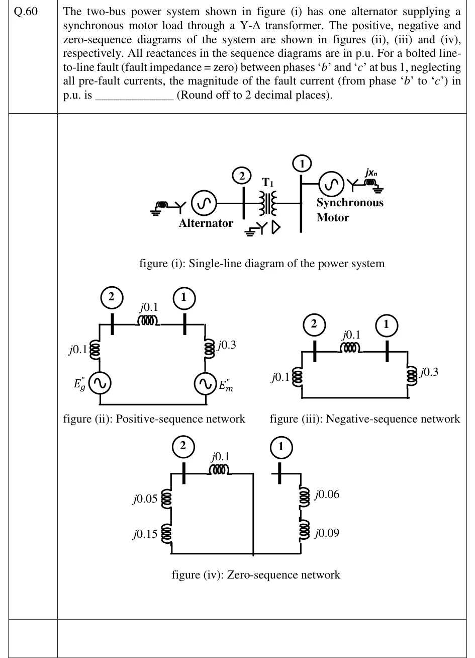
The two-bus power system shown in figure (i) has one alternator supplying a synchronous motor load through a Y-Δ transformer. The positive, negative and zero-sequence diagrams of the system are shown in figures (ii), (iii) and (iv), respectively. All reactances in the sequence diagrams are in p.u. For a bolted line-to-line fault (fault impedance = zero) between phases 'b' and 'c' at bus 1, neglecting all pre-fault currents, the magnitude of the fault current (from phase 'b' to 'c') in p.u. is ____________ (Round off to 2 decimal places).
 Tap to open full size
Figure description
Figure (i): single-line diagram. A grounded-Y alternator (with a reactor to ground) connects to bus 2; transformer T1 (grounded-Y on the bus 2 side, delta on the bus 1 side) connects bus 2 to bus 1; at bus 1 a synchronous motor (Y, grounded through reactance jXn) is connected. Figure (ii) positive sequence: Eg'' source in series with j0.1 up to bus 2; j0.1 between bus 2 and bus 1; at bus 1 a j0.3 reactance in series with the source Em'' returning to the reference. Figure (iii) negative sequence: same as (ii) but with no sources: j0.1 from bus 2 to reference, j0.1 between bus 2 and bus 1, j0.3 from bus 1 to reference. Figure (iv) zero sequence: at bus 2, j0.05 and j0.15 in series to reference; j0.1 between bus 2 and the transformer's zero-sequence break (the delta side is isolated from the line); at bus 1, j0.06 and j0.09 in series to reference, with no connection between the two sides.