
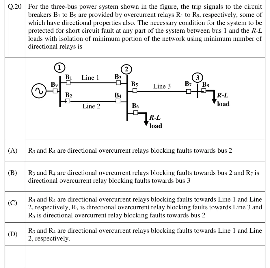
For the three-bus power system shown in the figure, the trip signals to the circuit breakers B1 to B9 are provided by overcurrent relays R1 to R9, respectively, some of which have directional properties also. The necessary condition for the system to be protected for short circuit fault at any part of the system between bus 1 and the R-L loads with isolation of minimum portion of the network using minimum number of directional relays is
 Tap to open full size
Figure description
Single-line diagram. A generator at the left connects through breaker B9 to bus 1. Two parallel lines run from bus 1 to bus 2: Line 1 (top) has B1 at the bus 1 end and B3 at the bus 2 end; Line 2 (bottom) has B2 at the bus 1 end and B4 at the bus 2 end. At bus 2, breaker B5 leads to Line 3, which runs to bus 3 with breaker B7 at the bus 3 end. Breaker B6 at bus 2 feeds an R-L load. At bus 3, breaker B8 feeds another R-L load. The only source is the generator at bus 1.
- (A)
R3 and R4 are directional overcurrent relays blocking faults towards bus 2
- (B)
R3 and R4 are directional overcurrent relays blocking faults towards bus 2 and R7 is directional overcurrent relay blocking faults towards bus 3
- (C)
R3 and R4 are directional overcurrent relays blocking faults towards Line 1 and Line 2, respectively, R7 is directional overcurrent relay blocking faults towards Line 3 and R5 is directional overcurrent relay blocking faults towards bus 2
- (D)
R3 and R4 are directional overcurrent relays blocking faults towards Line 1 and Line 2, respectively.