GATE 2025 EE Q.27
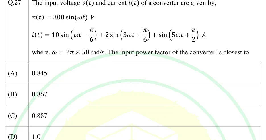
The input voltage and current of a converter are given by, V, A, where rad/s. The input power factor of the converter is closest to
- (A)
0.845
- (B)
0.867
- (C)
0.887
- (D)
1.0

IN THE EE SYLLABUS
A diode or thyristor rectifier draws a non-sinusoidal line current, so the supply sees harmonics, and reactive power when the converter is phase-controlled, even when the load current is pure DC. This topic gives the harmonic orders of single-phase and three-phase converters, their magnitudes and phases, and the displacement factor, distortion factor and power factor of fully controlled, half-controlled and uncontrolled (diode) bridges.
6 previous-year questions · 6 solved · 6 practice questions
Take a rectifier fed from an ideal, balanced, sinusoidal AC source. The load current is ripple-free (a very large load inductance) and conduction is continuous. The source inductance is zero unless an overlap angle is mentioned. The firing angle is measured from the natural commutation point, the instant a diode in the same position would start to conduct. is the peak of the supply phase voltage. is the rms supply voltage of a single-phase converter. is the rms line-to-line voltage of a three-phase supply. is the rms line (supply) current. A diode (uncontrolled) rectifier behaves like the matching fully controlled converter with .
Under these assumptions each thyristor (or diode) carries for a fixed part of the cycle, so the line current is a rectangular (square-type) wave. The DC side is smooth, and the AC side carries the harmonics.
AVERAGE OUTPUT VOLTAGE, SINGLE-PHASE FULLY CONTROLLED BRIDGE
Continuous conduction, zero source inductance.
AVERAGE OUTPUT VOLTAGE, THREE-PHASE FULLY CONTROLLED BRIDGE
Continuous conduction, zero source inductance. At this is the diode bridge value .
RMS LINE CURRENT, THREE-PHASE BRIDGE
In each cycle a line carries for , nothing for , for , and nothing for . With an ideal ripple-free this does not depend on .
The quasi-square line current of a six-pulse bridge has no even harmonics, because of half-wave symmetry. It also has no triplen harmonics (3rd, 9th, 15th, ...). The conduction blocks make each harmonic amplitude proportional to , which is zero for every multiple of 3. This agrees with the fact that a three-wire system gives balanced triplen (zero-sequence) currents no path. The only orders present are (), that is
In general, a -pulse converter with ripple-free has characteristic line-current harmonics of order and characteristic DC-side voltage harmonics of order . A twelve-pulse converter is two six-pulse bridges fed through star-star and star-delta transformers, with their DC outputs in series. Its supply current contains orders , because the 5th and 7th cancel.
LINE CURRENT OF PHASE A (SIX-PULSE BRIDGE)
Reference . At the positive block is centred on the positive peak of . For the whole waveform is the waveform delayed by . The peak of the -th term is . Zero overlap, ripple-free .
RMS FUNDAMENTAL LINE CURRENT, THREE-PHASE BRIDGE
The peak of the fundamental is . Divide by for the rms value.
RMS OF THE N-TH HARMONIC, THREE-PHASE BRIDGE
Six-pulse bridge, zero overlap, ripple-free . Relative to the fundamental the magnitude falls as , and it does not depend on .
Phase. Delaying the waveform by shifts the fundamental by and the -th harmonic by , each measured in its own cycle, since the argument is . So the fundamental current lags the phase voltage by . In a fully controlled bridge the harmonic magnitudes stay the same, and only their phases move with .
Order n | Rms relative to fundamental | Rms for pu |
|---|---|---|
1 | 1 | 0.780 |
5 | 0.200 | 0.156 |
7 | 0.143 | 0.111 |
11 | 0.091 | 0.071 |
13 | 0.077 | 0.060 |
LINE CURRENT, SINGLE-PHASE FULLY CONTROLLED BRIDGE
Reference . The current is a square wave of delayed by , so every odd order is present. Ripple-free , zero overlap. The magnitudes do not depend on .
LINE CURRENT, SINGLE-PHASE HALF-CONTROLLED BRIDGE
Half-controlled bridge (semi-converter), or a full bridge with a freewheeling diode, with ripple-free . The line current is from to , zero while the load freewheels, then from to . Here the harmonic magnitudes do depend on , and the fundamental lags the supply voltage by .
With a sinusoidal supply voltage, only the fundamental current carries average power. Harmonic currents add to the rms current without delivering average power, so they lower the power factor.
DISPLACEMENT FACTOR
is the phase angle between the supply voltage and the fundamental line current. With zero overlap, for a fully controlled bridge and for a single-phase half-controlled bridge.
DISTORTION FACTOR
The ratio of the fundamental rms current to the total rms line current. DF .
EXAM TIP
Names vary. Some texts write DF for the displacement factor, call the current distortion factor, and call the THD the harmonic factor. Use the definition the question gives.
INPUT POWER FACTOR
Sinusoidal supply voltage. For the three-phase case and . For the single-phase case and .
TOTAL HARMONIC DISTORTION OF THE LINE CURRENT
Harmonics are measured relative to the fundamental. Equivalently, .
SIX-PULSE BRIDGE, IDEAL INDUCTIVE LOAD
Fully controlled bridge, ripple-free , zero overlap. DF and THD do not change with . Only DPF does. A diode bridge () has PF .
SINGLE-PHASE HALF-CONTROLLED BRIDGE, IDEAL INDUCTIVE LOAD
Ripple-free , zero overlap. At this gives PF , the same as the full bridge. For its PF is higher than the full bridge's .
EXAM TIP
For the three-phase bridge the 0.955 factor comes entirely from distortion, and the factor from displacement. Do not multiply by twice, and do not apply to the DC-side power.
Increasing moves the whole current wave later, so the fundamental lags the voltage by more. With continuous conduction, a fully controlled converter draws lagging fundamental reactive power for every , in rectifier mode () and in inverter mode () alike. Active power changes sign at . stays positive: it rises to its maximum at and falls again towards .
POWER AND REACTIVE POWER, THREE-PHASE FULLY CONTROLLED BRIDGE
Zero overlap, lossless converter. is the fundamental reactive power. With , the fundamental apparent power is .
Overlap. With a source inductance per phase, the current edges no longer jump. They ramp over the overlap angle . This lowers the output voltage and delays the effective centre of the current wave, so the displacement angle is larger than . The sloping edges also generally reduce the magnitudes of the higher-order harmonics. The standard results are below.
OUTPUT VOLTAGE WITH OVERLAP, THREE-PHASE FULLY CONTROLLED BRIDGE
is the source inductance per phase, with ripple-free . For the single-phase fully controlled bridge the matching result is .
DISPLACEMENT FACTOR WITH OVERLAP (APPROXIMATE)
The ratio is approximately the displacement factor, since when is taken as its zero-overlap value. Use it only when a question involves overlap.
Quantity | Single-phase fully controlled bridge | Three-phase fully controlled bridge |
|---|---|---|
Line current wave | Square, | Quasi-square, blocks |
Harmonic orders | (all odd) | only |
(rms) | ||
Total rms | ||
DF | ||
THD | ||
PF | ||
WORKED EXAMPLE
A three-phase fully controlled bridge is fed from a 400 V (line-to-line, rms), 50 Hz supply with negligible source inductance. The load current is a constant 20 A and . Find the rms fundamental line current, the 5th and 7th harmonic currents, the rms line current, the input power factor, and the real and reactive power.
A.
A and A.
A.
and , so .
V. W.
var.
Check: VA and .
Answer: I_s1 = 15.59 A, I_5 = 3.12 A, I_7 = 2.23 A, I_s = 16.33 A, PF = 0.827 (lagging), P ≈ 9.36 kW, Q1 ≈ 5.40 kvar.
WORKED EXAMPLE
A single-phase fully controlled bridge supplies a ripple-free load current of 10 A with and zero source inductance. Find the 3rd harmonic current, the total harmonic distortion, and the input power factor.
The line current is a square wave of amplitude A, so A.
A, and A.
.
.
.
Answer: I_3 = 3.00 A, THD = 48.3 %, PF = 0.450 (lagging).
EXAM TIP
Orders present: a single-phase bridge gives all odd harmonics, and a three-phase six-pulse bridge gives only . With a balanced supply, triplen harmonics do not appear in the line current of the three-wire three-phase bridge.
EXAM TIP
In a fully controlled bridge with ideal ripple-free and no overlap, the harmonic magnitudes do not depend on . Only their phases change, along with the fundamental's displacement. So DF and THD are fixed and PF falls as .
EXAM TIP
In a half-controlled bridge the conduction width changes with , so the harmonic magnitudes, DF and THD all change with , and DPF , not .
EXAM TIP
Check which factor a question asks for. DF is , DPF is , and PF is their product. 'Power factor of the AC supply' means the full PF, including distortion.
EXAM TIP
A quick consistency test for the three-phase bridge: . When overlap is neglected, it must equal .
PREVIOUS-YEAR QUESTIONS
Try each question first, then open the answer. We placed each question under a topic ourselves; the exam paper does not label topics.
See these papers in full: GATE EE 2025 · GATE EE 2024 · GATE EE 2022 · GATE EE 2020 · GATE EE 2018
The input voltage and current of a converter are given by, V, A, where rad/s. The input power factor of the converter is closest to
0.845
0.867
0.887
1.0
A single-phase half-controlled bridge converter supplies an inductive load with ripple free load current. The triggering angle of the converter is 60°. The ratio of the rms value of the fundamental component of the input current to the rms value of the total input current of the bridge is __________ (rounded off to 3 decimal places).
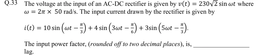
The voltage at the input of an AC-DC rectifier is given by where rad/s. The input current drawn by the rectifier is given by . The input power factor, (rounded off to two decimal places), is, ________ lag.
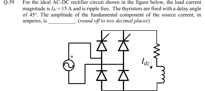
For the ideal AC-DC rectifier circuit shown in the figure below, the load current magnitude is A and is ripple free. The thyristors are fired with a delay angle of . The amplitude of the fundamental component of the source current, in amperes, is ______. (round off to two decimal places)
 Tap to open full size
Single-phase bridge fed from an AC source. Two legs: left and right. Each leg has a thyristor on top (anode toward the top rail, cathode-gate arrow drawn, upper devices) and a diode below it. The two upper devices are thyristors and the two lower devices are diodes. The AC source is connected between the midpoints of the two legs. The top rail joins the upper ends of both legs and goes to the load; the load is a resistor in series with an inductor, with I_dc flowing downward through it. The bottom rail returns from the lower ends of both legs to the load. This is a half-controlled (semi-converter) bridge with a highly inductive load.
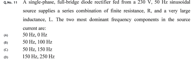
A single-phase, full-bridge diode rectifier fed from a 230 V, 50 Hz sinusoidal source supplies a series combination of finite resistance, R, and a very large inductance, L. The two most dominant frequency components in the source current are:
50 Hz, 0 Hz
50 Hz, 100 Hz
50 Hz, 150 Hz
150 Hz, 250 Hz
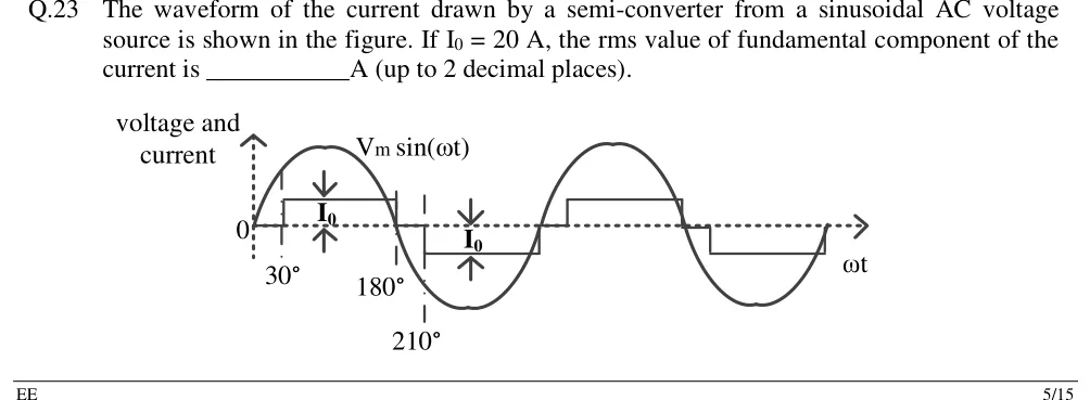
The waveform of the current drawn by a semi-converter from a sinusoidal AC voltage source is shown in the figure. If A, the rms value of fundamental component of the current is ______ A (up to 2 decimal places).
 Tap to open full size
Horizontal axis ω t, vertical axis 'voltage and current'. A sinusoid V_m sin (ω t) is drawn for two cycles. The current is a quasi-square wave of height I_0: zero from 0 to 30°, +I_0 from 30° to 180°, zero from 180° to 210°, -I_0 from 210° to 360°; the second cycle repeats this. Marked instants: 30°, 180°, 210°; I_0 marked with arrows on both levels.
PRACTICE
A three-phase fully controlled bridge rectifier feeds a highly inductive load (ripple-free ) from a balanced supply. The source inductance is negligible. Which set lists the lowest four harmonic orders present in the line current?
3, 5, 7, 9
5, 7, 11, 13
2, 4, 6, 8
3, 6, 9, 12
Answer: (B)
Half-wave symmetry rules out even harmonics.
The blocks make the amplitude proportional to , which is zero for multiples of 3, so there are no triplen harmonics.
The orders present are : 5, 7, 11, 13, ...
A three-phase diode bridge rectifier supplies a ripple-free load current of 30 A. Source inductance is negligible. Find the rms value of the 11th harmonic of the line current, in amperes. Give your answer correct to two decimal places.
Answer: (accepted range )
A.
A.
A three-phase fully controlled bridge converter operates with a firing angle of and a ripple-free load current. Source inductance is negligible and the supply is sinusoidal. Find the power factor at the AC input. Give your answer correct to three decimal places.
Answer: (accepted range )
.
.
.
A single-phase fully controlled bridge is supplied from a 230 V rms, 50 Hz source with negligible source inductance. The load current is a constant 10 A and the firing angle is . Find the reactive power drawn at the fundamental frequency, in var. Give your answer to the nearest whole number.
Answer: (accepted range )
The line current is a square wave of amplitude 10 A, so A.
The fundamental lags the voltage by .
var.
For a three-phase fully controlled bridge with a balanced supply, a ripple-free load current and negligible source inductance, which of the following statements are correct?
The line current contains no 3rd or 9th harmonic.
The fundamental line current lags the phase voltage by the firing angle .
The distortion factor decreases as increases.
The total harmonic distortion of the line current is about 31% for every .
Answer: (A), (B), (D)
A is true. The blocks give zero amplitude for every multiple of 3.
B is true. The current wave is the wave delayed by , so .
C is false. DF for every , because the harmonic magnitudes do not change.
D is true. THD for all .
A single-phase half-controlled bridge (semi-converter) supplies a ripple-free load current from a sinusoidal source with negligible source inductance. The firing angle is . Find the input power factor. Give your answer correct to three decimal places.
Answer: (accepted range )
The line current is for in each half-cycle, so .
.
, and .
.
OFFICIAL GATE 2027 SYLLABUS WORDING
Copied from the GATE 2027 syllabus; see all 2027 syllabi.
GATE EE
Magnitude and Phase of line current harmonics for uncontrolled and thyristor based converters; Power factor and Distortion Factor of AC to DC converters
Preparing in Kolkata? IAE Academy's course for GATE EE.