IAE Academy

GATE EE · IN

Uncontrolled and controlled rectifiers, AC-DC converters

How diodes and thyristors turn AC into DC: average and rms output, ripple, the effect of the firing angle, source inductance and overlap, inversion, thyristor commutation, and the converters built from them (dual converters, AC voltage controllers, PWM voltage source converters and DC drives). Every result is given with the conduction assumption it needs, because the same circuit gives a different output under a different assumption.

12 previous-year questions · 11 solved · 7 practice questions

Single-phase uncontrolled rectifiers

Conventions: is the peak of the supply voltage, is its rms value, the diodes are ideal and the load is resistive unless stated. Average output is and rms output is . Form factor is . Ripple factor is , where is the rms of the output with its average removed.

RIPPLE FACTOR FROM FORM FACTOR

Holds for any output waveform; is the total rms including the DC part.

HALF-WAVE RECTIFIER, R LOAD

One diode conducts for 180 degrees of each cycle.

FULL-WAVE RECTIFIER (CENTRE-TAP OR BRIDGE), R LOAD

For the centre-tap type is the peak of each half of the secondary. PIV is for the bridge and for the centre-tap.

Quantity

Half-wave

Full-wave bridge

Full-wave centre-tap

(R load)

(R load)

Ripple factor

1.21

0.483

0.483

Diodes

1

4

2

PIV per diode

Output ripple frequency

HALF-WAVE RECTIFIER, RL LOAD (NO FREEWHEELING DIODE)

. The current is with . The current continues after the supply goes negative, up to the extinction angle where , so the output voltage has a negative portion from to .

A freewheeling diode across the load removes the negative portion. returns to and the load current becomes smoother. With a very large load inductance, the bridge output current is constant at . The source current is then a square wave of height , with rms value and fundamental rms value , so the input power factor is .

HALF-WAVE DIODE CHARGING A BATTERY $E$ THROUGH $R$ (NO INDUCTANCE)

The diode conducts only while the instantaneous supply voltage exceeds , from to . In a full-wave bridge the same interval repeats in every half cycle, so the average current doubles.

EXAM TIP

With an R + E load and no inductance, current flows only while . Find first; the conduction angle is in each conducting half cycle.

Three-phase uncontrolled rectifiers

Convention: is the peak of the phase voltage and is the peak of the line voltage. without a subscript is the rms line voltage. The load current is continuous and ripple-free () unless stated.

THREE-PHASE HALF-WAVE (3-PULSE) DIODE RECTIFIER

Each diode conducts for 120 degrees; its average current is and its rms current is . The output ripple frequency is .

THREE-PHASE BRIDGE (6-PULSE) DIODE RECTIFIER

The output is made of six line-voltage segments per cycle, so the ripple frequency is . PIV .

BRIDGE CURRENTS WITH CONSTANT $I_{DC}$

Each diode conducts 120 degrees. The line current has one positive and one negative 120-degree block per cycle, and its fundamental is .

  1. At any instant the top diode connected to the phase with the highest voltage and the bottom diode connected to the phase with the lowest voltage conduct.

  2. The output equals the largest line-to-line voltage at that instant.

  3. Each line-voltage segment lasts 60 degrees, and the conducting diode pair changes every 60 degrees.

EXAM TIP

For the bridge, where is the rms line voltage. For the half-wave circuit use the phase voltage: with in rms.

Single-phase phase-controlled rectifiers

Convention: the firing angle is measured from the natural commutation point, which is the instant a diode in the same position would start conducting. For a single-phase supply this is the zero crossing of the supply voltage. Continuous conduction is assumed unless stated.

HALF-WAVE CONTROLLED RECTIFIER, R LOAD

Applies to an R load and also to an RL load with a freewheeling diode. Range .

CONTROLLED RECTIFIERS WITH R LOAD: RMS OUTPUT

Pure R load, so the output follows the supply from to in each conducting half cycle. The bridge result holds for both the fully controlled and the half-controlled bridge.

FULLY CONTROLLED BRIDGE, CONTINUOUS CONDUCTION (LARGE L)

Positive for (rectification) and negative for (inversion, which needs an active load such as a reversed battery or a regenerating machine). With an RLE load and continuous current, .

HALF-CONTROLLED BRIDGE, OR FULLY CONTROLLED BRIDGE WITH R LOAD OR FREEWHEELING DIODE

The output cannot go negative, so only the rectifying quadrant is available.

FULLY CONTROLLED BRIDGE WITH LARGE L: SOURCE CURRENT

Square-wave source current; each thyristor conducts for 180 degrees, with average current and rms current . The source current has odd harmonics with , and THD . Input powers: and .

HALF-CONTROLLED BRIDGE WITH LARGE L: SOURCE CURRENT

The source current is from to , from to , and zero while the load freewheels. Its displacement factor is better than the fully controlled bridge's .

Circuit

Quadrant(s)

Output-voltage range

Half-wave controlled (R load, or RL with a freewheeling diode)

1 only

to

Half-controlled bridge (any load)

1 only

to

Fully controlled bridge, large L

1 and 4 (two-quadrant converter)

to

WORKED EXAMPLE

A single-phase fully controlled bridge is fed from a 230 V, 50 Hz supply. The load current is constant at 10 A and the firing angle is 60 degrees. Source inductance is negligible. Find the average output voltage, the output power and the input power factor.

Solution
  1. V.

  2. V.

  3. W.

  4. .

Answer: V, W, lagging.

EXAM TIP

For an R load the bridge output is , not . The cosine law holds only when the load current is continuous, which in practice needs enough load inductance.

Three-phase controlled rectifiers

Convention: is the peak phase voltage and is the peak line voltage. In a three-phase circuit the natural commutation point is where two phase voltages cross, 30 degrees after the zero crossing of the phase voltage. The firing angle is measured from there. Each thyristor in a bridge conducts for 120 degrees when conduction is continuous.

THREE-PHASE FULLY CONTROLLED BRIDGE, CONTINUOUS CONDUCTION

Negative for , which is inversion. The load current stays continuous for all when is large enough.

THREE-PHASE HALF-CONTROLLED BRIDGE

The output never goes negative, so gives rectification only.

THREE-PHASE HALF-WAVE CONTROLLED CONVERTER

Continuous conduction. Each thyristor conducts 120 degrees.

THREE-PHASE HALF-WAVE, R LOAD, DISCONTINUOUS ($\ALPHA>30^\CIRC$)

Valid for ; the output reaches zero at . For with an R load the current stays continuous and the cosine law holds.

FULLY CONTROLLED BRIDGE, R LOAD, DISCONTINUOUS ($\ALPHA>60^\CIRC$)

Valid for ; the output reaches zero at . For with an R load the output stays positive and the cosine law still holds.

The bridge firing order is in steps of 60 degrees, with each thyristor fired 120 degrees after the previous one in its own half of the bridge.

THREE-PHASE FULLY CONTROLLED BRIDGE WITH LARGE L: SOURCE CURRENT

The line current has one positive and one negative 120-degree block per cycle. Its harmonics are of order () with , and THD . Input powers: and .

EXAM TIP

When is just above 60 degrees, check whether the problem has an RL load with large (use ) or a pure R load (use the form).

Source inductance, overlap and inversion

With source inductance the current cannot change instantly, so the outgoing and incoming devices conduct together during commutation, for an overlap angle . During overlap the output voltage is the average of the outgoing and incoming voltages. In a single-phase bridge this average is zero, because all four thyristors conduct and short the supply. As a result drops. Here is constant and is the supply angular frequency.

SINGLE-PHASE FULLY CONTROLLED BRIDGE WITH $L_S$

Large L, continuous conduction. The drop equals and does not depend on .

THREE-PHASE FULLY CONTROLLED BRIDGE WITH $L_S$

Constant ; is per phase. The drop equals .

THREE-PHASE HALF-WAVE CONVERTER WITH $L_S$

Three commutations per cycle, each driven by the line voltage between the two phases involved.

Inversion: for the average converter output voltage is negative while the current stays positive, so power flows from the DC side to the AC side. This needs a DC source in the load that drives the current against the negative converter voltage, such as a DC machine regenerating. The extinction angle is , and the outgoing thyristor is reverse-biased for . If is less than the thyristor turn-off time , the outgoing thyristor is forward-biased again before it has recovered. It then resumes conduction and commutation fails. The firing angle must therefore satisfy .

WORKED EXAMPLE

A three-phase fully controlled bridge is supplied from a 400 V (rms line), 50 Hz source with per phase. The load current is a constant 50 A and . Find the average output voltage and the overlap angle.

Solution
  1. V.

  2. Ideal output: V.

  3. Drop: V.

  4. V.

  5. , so .

  6. , so .

Answer: V and .

EXAM TIP

The overlap formula uses with the peak of the voltage driving the commutation: for a single-phase bridge and for a three-phase bridge.

Thyristor commutation: line, voltage and current commutation

A thyristor turns off when its current falls below the holding current and it is then kept reverse-biased for longer than its turn-off time . The time for which the circuit reverse-biases it is the circuit turn-off time , and the requirement is . In a phase-controlled converter the AC supply does this: when the next thyristor is fired, the supply voltage reverse-biases the outgoing one. This is natural, or line, commutation, and its circuit turn-off time is . Where no alternating voltage is available, for example in a thyristor chopper or inverter, a forced-commutation circuit turns the thyristor off.

VOLTAGE (IMPULSE) COMMUTATION

An auxiliary thyristor switches a capacitor , charged to , across the conducting thyristor, reverse-biasing it at once. With the load current constant during commutation, the capacitor voltage changes linearly from to zero in time .

CURRENT (RESONANT-PULSE) COMMUTATION

An LC circuit drives a resonant current pulse of peak through the thyristor, opposite to its load current , assumed constant during commutation. The thyristor current reaches zero when the pulse reaches . A diode across the thyristor then carries the excess, and its forward drop reverse-biases the thyristor until the pulse falls back to . Commutation needs .

Dual converters, AC voltage controllers, voltage source converters and DC drives

A dual converter is two fully controlled converters connected back-to-back across one load. One carries positive current and the other carries negative current, so the drive can work in all four quadrants. The two firing angles satisfy . Their average output voltages are then equal at the load terminals, with one converter rectifying and the other inverting. Their instantaneous voltages still differ. In the circulating-current mode both converters conduct all the time, with a reactor between them to limit the circulating current that this difference drives. In the non-circulating mode only the converter that carries the load current is gated.

AC VOLTAGE CONTROLLER, R LOAD (SINGLE-PHASE, PHASE CONTROL)

Two antiparallel thyristors (or a triac), fired symmetrically. is the rms supply voltage and is measured from the voltage zero crossing. Control range . The output has no DC component. Input power factor .

With an RL load the load angle is , and phase control works for . For with a sustained gate signal or a pulse train, the load current is a continuous sinusoid lagging by . The full supply voltage then appears across the load, so firing control is lost. With a single short gate pulse and , only one thyristor conducts, and the load current then has a DC component.

BIDIRECTIONAL AC-DC VOLTAGE SOURCE CONVERTER (PWM RECTIFIER)

Per phase, with a lossless line reactance . is the rms source voltage, is the rms fundamental converter voltage, and is the angle by which leads . is the reactive power sent by the source. For a three-phase converter, multiply both by 3 when phase rms values are used. gives power flow from AC to DC (rectification) and gives power flow from DC to AC (regeneration).

A voltage source converter uses fully controlled switches with antiparallel diodes and a DC-link capacitor. It can draw a nearly sinusoidal current at unity power factor, and it lets power flow in either direction. The DC-link voltage must exceed the peak supply voltage: for a single-phase converter and for a three-phase one. Below that, the antiparallel diodes conduct as an uncontrolled diode bridge, and the current can no longer be controlled. The converter therefore works as a boost rectifier. In contrast, a thyristor converter draws a current whose fundamental lags by , and it can invert only when an opposing DC source drives the current.

RECTIFIER-FED SEPARATELY EXCITED DC MOTOR

Steady state with continuous armature current. Speed is raised by increasing (reducing ).

Drive converter

Quadrants

Notes

Single-phase half-controlled bridge

1

Motoring only, no regeneration

Single-phase fully controlled bridge

1 and 4

Regeneration (as inverter) when with a reversed

Dual converter

1, 2, 3 and 4

Both directions of speed and torque

EXAM TIP

A fully controlled converter gives of either sign but only. with means power flows from the machine to the supply. This needs reversed, for example by an overhauling load driving the motor backwards, and it is regenerative braking.

PREVIOUS-YEAR QUESTIONS

12 questions from the EE papers

Try each question first, then open the answer. We placed each question under a topic ourselves; the exam paper does not label topics.

See these papers in full: GATE EE 2026 · GATE EE 2025 · GATE EE 2024 · GATE EE 2023 · GATE EE 2022 · GATE EE 2020 · GATE EE 2018

GATE 2026 EE Q.34

GATE 2026 · EEQ.34 · 1 mark · NAT

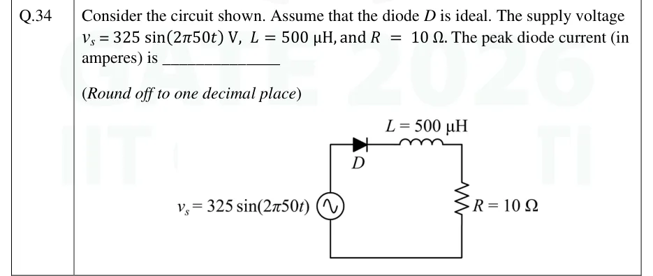
Consider the circuit shown. Assume that the diode D is ideal. The supply voltage v_s = 325 sin(2π50t) V, L = 500 µH, and R = 10 Ω. The peak diode current (in amperes) is ______________ (Round off to one decimal place)
GATE 2026 EE question 34: A single series loop.Tap to open full size
Figure from the GATE 2026 EE paper. It is part of the question.
Figure description

A single series loop. An AC voltage source v_s = 325 sin(2π50t) V is on the left (vertical branch). From its top terminal the path goes up and right through the ideal diode D (anode toward the source, cathode toward the right, arrow pointing right), then through the inductor L = 500 µH along the top, then down through the resistor R = 10 Ω on the right, and returns along the bottom wire to the source. There is no freewheeling diode and no other element.
Answer and solution
GATE 2026 EE Q.34: answer and solution

GATE 2026 EE Q.61

GATE 2026 · EEQ.61 · 2 marks · NAT

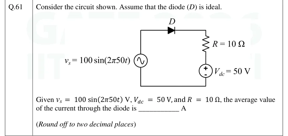
Consider the circuit shown. Assume that the diode (D) is ideal. Given V, V, and , the average value of the current through the diode is ____ A (Round off to two decimal places).

GATE 2026 EE question 61: A single series loop.Tap to open full size
Figure from the GATE 2026 EE paper. It is part of the question.
Figure description

A single series loop. AC source v_s = 100 sin (2 π 50t) on the left branch. Top branch: ideal diode D with anode toward the source (left) and cathode toward the right, so it conducts when current flows from the source to the right. Right branch going down: resistor R = 10 Ω, then a DC battery V_dc = 50 V with its + terminal at the top (next to R) and - terminal at the bottom. The bottom wire returns to the source.

Answer and solution
GATE 2026 EE Q.61: answer and solution

GATE 2025 EE Q.47

GATE 2025 · EEQ.47 · 2 marks · MCQ

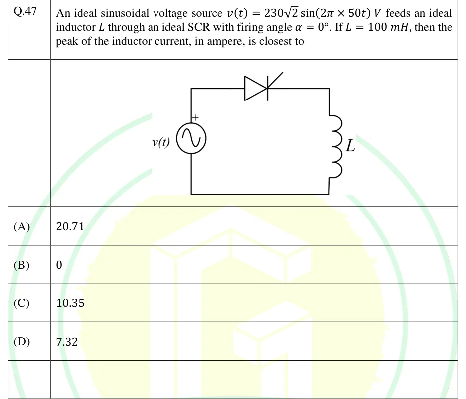
An ideal sinusoidal voltage source V feeds an ideal inductor through an ideal SCR with firing angle . If mH, then the peak of the inductor current, in ampere, is closest to

GATE 2025 EE question 47: Single loop.Tap to open full size
Figure from the GATE 2025 EE paper. It is part of the question.
Figure description

Single loop. The AC source v(t) (sine symbol, + terminal at the top) is on the left. From its + terminal the top wire runs right through an SCR (thyristor) whose anode is on the source side and cathode on the right, with the gate lead drawn on the upper right of the symbol. The wire then turns down into the inductor L on the right side. The bottom wire returns from the inductor to the source's negative terminal.

  1. (A)

    20.71

  2. (B)

    0

  3. (C)

    10.35

  4. (D)

    7.32

Answer and solution
GATE 2025 EE Q.47: answer and solution

GATE 2025 EE Q.48

GATE 2025 · EEQ.48 · 2 marks · MCQ

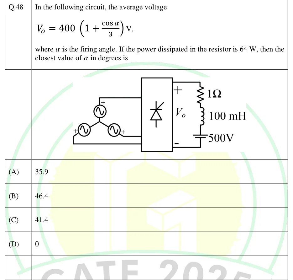
In the following circuit, the average voltage V, where is the firing angle. If the power dissipated in the resistor is 64 W, then the closest value of in degrees is

GATE 2025 EE question 48: A three-phase star-connected AC source (three sinusoidal sources joined at a common star point) feeds a box containing a…Tap to open full size
Figure from the GATE 2025 EE paper. It is part of the question.
Figure description

A three-phase star-connected AC source (three sinusoidal sources joined at a common star point) feeds a box containing a thyristor symbol, a three-phase thyristor converter. The outer terminals of all three sources are wired to the left side of the box: one from the top source, and two from the lower left and lower right sources. The output voltage V_o is marked with + at the top and - at the bottom on the right of the box. The load across V_o is, in series from top to bottom, a 1 ohm resistor, a 100 mH inductor and a 500 V DC source.

  1. (A)

    35.9

  2. (B)

    46.4

  3. (C)

    41.4

  4. (D)

    0

Answer and solution
GATE 2025 EE Q.48: answer and solution

GATE 2024 EE Q.65

GATE 2024 · EEQ.65 · 2 marks · NAT

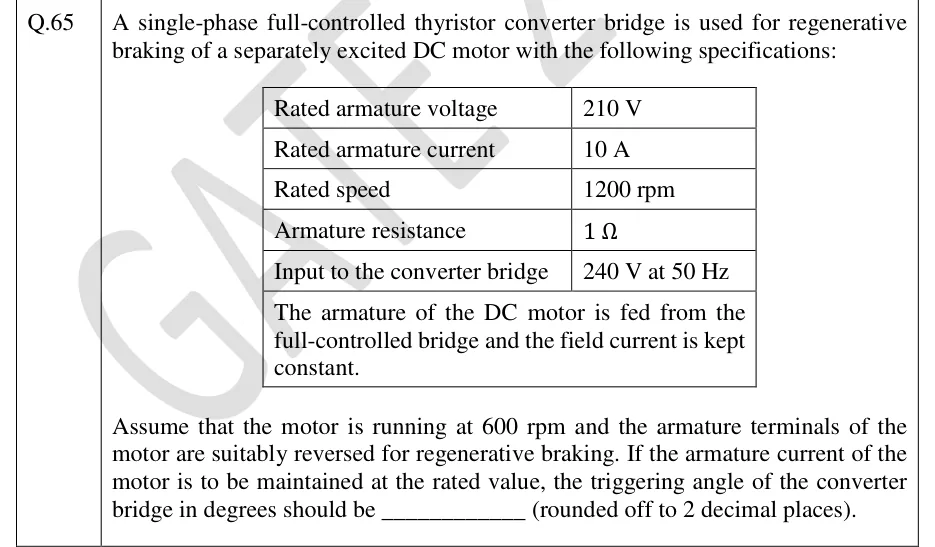
A single-phase full-controlled thyristor converter bridge is used for regenerative braking of a separately excited DC motor with the following specifications: rated armature voltage 210 V; rated armature current 10 A; rated speed 1200 rpm; armature resistance 1 Ω; input to the converter bridge 240 V at 50 Hz. The armature of the DC motor is fed from the full-controlled bridge and the field current is kept constant. Assume that the motor is running at 600 rpm and the armature terminals of the motor are suitably reversed for regenerative braking. If the armature current of the motor is to be maintained at the rated value, the triggering angle of the converter bridge in degrees should be ____________ (rounded off to 2 decimal places).

Answer and solution
See the question in the paper
GATE 2024 EE Q.65: answer and solution

GATE 2023 EE Q.58

GATE 2023 · EEQ.58 · 2 marks · NAT

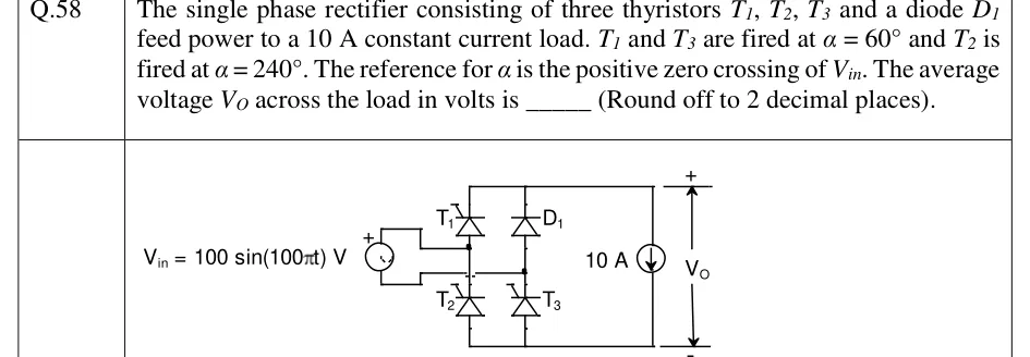
The single phase rectifier consisting of three thyristors , , and a diode feed power to a 10 A constant current load. and are fired at and is fired at . The reference for is the positive zero crossing of . The average voltage across the load in volts is _____ (Round off to 2 decimal places).

GATE 2023 EE question 58: Bridge with two legs between a top rail and a bottom rail.Tap to open full size
Figure from the GATE 2023 EE paper. It is part of the question.
Figure description

Bridge with two legs between a top rail and a bottom rail. Left leg: T1 on top, T2 below. Right leg: D1 on top, T3 below. The source V_in = 100 sin (100 π t) V (the + terminal marked on the upper side) is connected between the midpoint of the left leg (T1/T2 junction) and the midpoint of the right leg (D1/T3 junction). A 10 A constant current source is the load between the top rail and the bottom rail, arrow pointing down. V_O is measured across it with + at the top rail.

Answer and solution
GATE 2023 EE Q.58: answer and solution

GATE 2020 EE Q.12

GATE 2020 · EEQ.12 · 1 mark · MCQ

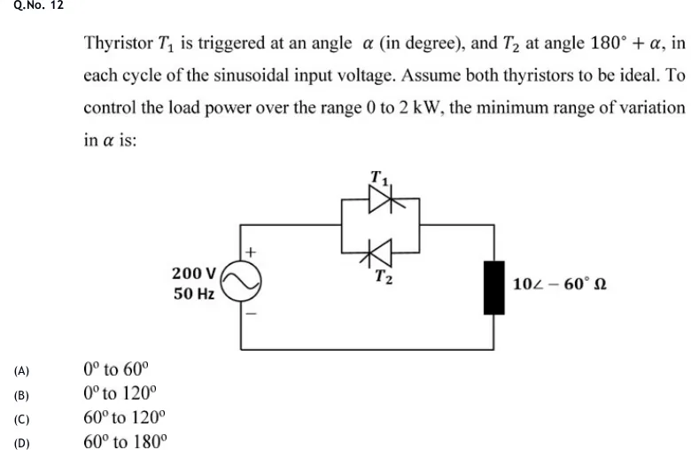
Thyristor is triggered at an angle (in degree), and at angle , in each cycle of the sinusoidal input voltage. Assume both thyristors to be ideal. To control the load power over the range 0 to 2 kW, the minimum range of variation in is:

GATE 2020 EE question 12: Single-phase AC voltage controller.Tap to open full size
Figure from the GATE 2020 EE paper. It is part of the question.
Figure description

Single-phase AC voltage controller. A 200 V, 50 Hz sinusoidal source (plus terminal at the top) feeds a load through two anti-parallel thyristors, T1 (upper) and T2 (lower), connected in parallel in the top line. The load, drawn as a black block on the right, is the impedance 10∠-60° Ω. The circuit is closed through the bottom wire back to the source.

  1. (A)

    0° to 60°

  2. (B)

    0° to 120°

  3. (C)

    60° to 120°

  4. (D)

    60° to 180°

Official answer

Official answer: marks to all candidatesSource: Official answer key, GATE 2020 EE (IIT Delhi)

GATE 2020 EE Q.12: official answer

GATE 2020 EE Q.51

GATE 2020 · EEQ.51 · 2 marks · NAT

A single-phase, full-bridge, fully controlled thyristor rectifier feeds a load comprising a 10 Ω resistance in series with a very large inductance. The rectifier is fed from an ideal 230 V, 50 Hz sinusoidal source through cables which have negligible internal resistance and a total inductance of 2.28 mH. If the thyristors are triggered at an angle α = 45°, the commutation overlap angle in degree (rounded off to 2 decimal places) is ______.

Answer and solution
See the question in the paper
GATE 2020 EE Q.51: answer and solution

GATE 2018 EE Q.3

GATE 2018 · EEQ.3 · 1 mark · MCQ

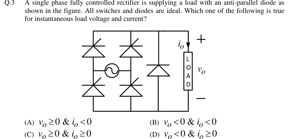
A single phase fully controlled rectifier is supplying a load with an anti-parallel diode as shown in the figure. All switches and diodes are ideal. Which one of the following is true for instantaneous load voltage and current?

GATE 2018 EE question 3: A single-phase thyristor bridge fed by an AC source (sine symbol) connected between the two mid-points of the two bridge…Tap to open full size
Figure from the GATE 2018 EE paper. It is part of the question.
Figure description

A single-phase thyristor bridge fed by an AC source (sine symbol) connected between the two mid-points of the two bridge legs. Left leg: upper and lower thyristors; right leg: upper and lower thyristors. The upper thyristors have their cathodes joined to the top (positive) output rail and the lower thyristors have their anodes joined to the bottom (negative) rail. Across the DC output, between the top and bottom rails, is a diode with its cathode on the top rail and anode on the bottom rail (anti-parallel to the load, i.e. a freewheeling diode). The load (boxed, labelled LOAD) is connected between the rails, with load current i_o drawn downward through it from the top rail, and load voltage v_o marked + at the top and - at the bottom.

  1. (A)

    v_o ≥ 0 & i_o < 0

  2. (B)

    v_o < 0 & i_o < 0

  3. (C)

    v_o ≥ 0 & i_o ≥ 0

  4. (D)

    v_o < 0 & i_o ≥ 0

Answer and solution
GATE 2018 EE Q.3: answer and solution

GATE 2018 EE Q.49

GATE 2018 · EEQ.49 · 2 marks · NAT

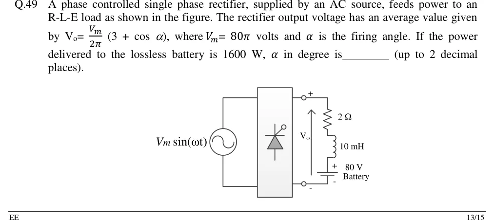
A phase controlled single phase rectifier, supplied by an AC source, feeds power to an R-L-E load as shown in the figure. The rectifier output voltage has an average value given by , where volts and is the firing angle. If the power delivered to the lossless battery is 1600 W, in degree is ________ (up to 2 decimal places).

GATE 2018 EE question 49: Source V_m sin (ω t) on the left feeds a rectifier block (a box containing a single thyristor symbol with a gate terminal).Tap to open full size
Figure from the GATE 2018 EE paper. It is part of the question.
Figure description

Source V_m sin (ω t) on the left feeds a rectifier block (a box containing a single thyristor symbol with a gate terminal). The block's output terminals (+ at top, - at bottom) carry V_o (arrow pointing up). Across the output is a series load: a 2 ohm resistor, a 10 mH inductor, and a battery of 80 V with its + terminal at the top (towards the inductor) and - at the bottom.

Answer and solution
GATE 2018 EE Q.49: answer and solution

PRACTICE

7 questions to test yourself

PRACTICE 11 mark · NAT

A single-phase full-wave bridge diode rectifier is fed from a 230 V rms, 50 Hz supply. The load is purely resistive and the diodes are ideal. Find the average output voltage in volts, correct to one decimal place.

Answer and solution

Answer: (accepted range )

  1. V.

  2. V.

PRACTICE 22 marks · MCQ

A three-phase fully controlled thyristor bridge is fed from a 400 V rms line-to-line supply. The load contains a DC source that keeps the load current large and continuous. Source inductance is negligible. The firing angle is 120 degrees. The average output voltage is closest to which of the following?

  1. (A)

    +270 V

  2. (B)

    -270 V

  3. (C)

    -540 V

  4. (D)

    0 V

Answer and solution

Answer: (B)

  1. V.

  2. V.

  3. The converter is in the inverting mode, so the answer is V.

PRACTICE 32 marks · MSQ

A single-phase fully controlled thyristor bridge supplies a highly inductive load with constant current, with and negligible source inductance. Which of the following statements are correct?

  1. (A)

    The average output voltage is positive and equals .

  2. (B)

    The rms value of the source current equals the load current.

  3. (C)

    The displacement factor of the fundamental source current is .

  4. (D)

    Each thyristor conducts for 90 degrees in a cycle.

Answer and solution

Answer: (A), (B), (C)

  1. A is true: , so .

  2. B is true: the source current is a square wave of height , so its rms value is .

  3. C is true: the fundamental lags the supply by .

  4. D is false: with continuous conduction each thyristor conducts for 180 degrees.

PRACTICE 42 marks · NAT

A single-phase AC voltage controller using two antiparallel thyristors supplies a 10 ohm resistor from a 230 V rms, 50 Hz source. The firing angle of each thyristor is 90 degrees. Find the power delivered to the resistor in watts.

Answer and solution

Answer: (accepted range )

  1. .

  2. At : , so V.

  3. W.

PRACTICE 52 marks · NAT

A single-phase fully controlled bridge is fed from a 230 V rms, 50 Hz supply through a source inductance of 2 mH. The load current is constant at 20 A and the firing angle is 30 degrees. Find the average output voltage in volts, correct to one decimal place.

Answer and solution

Answer: (accepted range )

  1. V and .

  2. Ideal output: V.

  3. Drop: V.

  4. V.

PRACTICE 62 marks · NAT

A single-phase half-controlled bridge supplies a highly inductive load with constant, ripple-free current. Source inductance is negligible and the firing angle is 60 degrees. Find the input power factor, correct to two decimal places.

Answer and solution

Answer: (accepted range )

  1. Source current: from to and from to , so .

  2. .

  3. Displacement factor .

  4. .

  5. Check: .

PRACTICE 72 marks · NAT

A thyristor carrying a constant load current of 100 A is turned off by a resonant-pulse (current) commutation circuit with H and F, the capacitor being initially charged to 200 V. A diode across the thyristor carries the resonant current in excess of the load current. Find the circuit turn-off time in microseconds, correct to one decimal place.

Answer and solution

Answer: (accepted range )

  1. A, which exceeds A, so commutation succeeds.

  2. s.

  3. rad.

  4. s.

OFFICIAL GATE 2027 SYLLABUS WORDING

Copied from the GATE 2027 syllabus; see all 2027 syllabi.

GATE EE

Single and three-phase configuration of uncontrolled rectifiers; Voltage and Current commutated Thyristor based converters; Bidirectional ac to dc voltage source converters

GATE IN

rectifiers

Preparing in Kolkata? IAE Academy's course for GATE EE or GATE IN.