
IAE Academy

GATE 2018 EE Q.3: solution and answer

GATE 2018 · EEQ.3 · 1 mark · MCQ

A single phase fully controlled rectifier is supplying a load with an anti-parallel diode as shown in the figure. All switches and diodes are ideal. Which one of the following is true for instantaneous load voltage and current?
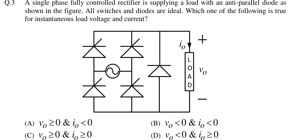
GATE 2018 EE question 3: A single-phase thyristor bridge fed by an AC source (sine symbol) connected between the two mid-points of the two bridge…Tap to open full size
Figure from the GATE 2018 EE paper. It is part of the question.
Figure description

A single-phase thyristor bridge fed by an AC source (sine symbol) connected between the two mid-points of the two bridge legs. Left leg: upper and lower thyristors; right leg: upper and lower thyristors. The upper thyristors have their cathodes joined to the top (positive) output rail and the lower thyristors have their anodes joined to the bottom (negative) rail. Across the DC output, between the top and bottom rails, is a diode with its cathode on the top rail and anode on the bottom rail (anti-parallel to the load, i.e. a freewheeling diode). The load (boxed, labelled LOAD) is connected between the rails, with load current i_o drawn downward through it from the top rail, and load voltage v_o marked + at the top and - at the bottom.

  1. (A)

    v_o ≥ 0 & i_o < 0

  2. (B)

    v_o < 0 & i_o < 0

  3. (C)

    v_o ≥ 0 & i_o ≥ 0

  4. (D)

    v_o < 0 & i_o ≥ 0

Answer and solution

ANSWER

and , which is option (C).

Official answer: CSource: Official answer key, GATE 2018 EE (IIT Guwahati)

  1. The circuit is a single-phase fully controlled bridge of four thyristors, with a diode across the DC output. has its cathode on the top (positive) rail and its anode on the bottom rail, so it is a freewheeling diode. The firing angle may take any value. The duty ratio of depends on and the load, and the argument below does not need it.

  2. Current direction: thyristors and diodes conduct only from anode to cathode. The upper devices have their cathodes on the top rail and the lower devices have their anodes on the bottom rail. So the bridge can only push current into the top rail and out of the bottom rail, and only carries current from the bottom rail to the top rail, in parallel with the load. The load current is drawn downward through the load, so it is the sum of the bridge current and the current, both non-negative. Hence at every instant. Option (A) and option (B) are therefore ruled out.

  3. Voltage limit: is the voltage from the top rail to the bottom rail. If tried to become negative, the top rail would be below the bottom rail. would then be forward biased, because its anode is on the bottom rail and its cathode is on the top rail. An ideal diode in conduction holds . So can never be negative.

  4. While a diagonal pair of thyristors conducts, the output is the rectified source voltage, for the pair that conducts in the positive half cycle, and for the other pair in the negative half cycle. Both are non-negative. When the thyristors stop conducting, the load current freewheels through and .

  5. So at every instant and . This is option (C). The bridge is effectively a half-controlled rectifier, because the freewheeling diode removes the negative-voltage (inverting) interval.

KEY IDEA

A bridge of thyristors can only carry current in one direction, so . An ideal freewheeling diode across the output clamps at whenever it would go negative, so . Together these give and .

WATCH OUT FOR

Treating this as an ordinary fully controlled bridge, where goes negative after for with an inductive load (inverter-like operation). The anti-parallel diode across the load removes that interval. Another slip is to read the diode as reversing the load current. It cannot, because every device in the circuit conducts in one direction only.

From the GATE 2018 EE paper. Every question of this paper · Download the full paper · All 12 Rectifiers questions, with notes

More Rectifiers questions