IAE Academy

GATE EE · IN

Inverters and pulse width modulation

An inverter turns a dc supply into an ac output of chosen magnitude and frequency, and pulse width modulation (PWM) shapes that output. This topic covers the rms values and harmonics of square-wave, quasi-square and six-step waveforms, the modulation ratios of sinusoidal PWM, current source inverters, V/f control of induction motors, and the sensors used in drives.

6 previous-year questions · 6 solved · 7 practice questions

Single-phase voltage source inverters

A voltage source inverter (VSI) is fed from a stiff dc voltage and its switches force the output voltage. Conventions: is the total dc input, the load is passive, rms is over one output cycle, and in square-wave operation each switch conducts for 180° of the output cycle.

Half-bridge: two switches and a split source (each half ); output swings between and . Full-bridge: four switches, diagonal pairs conduct alternately; output swings between and . With an inductive load the current lags the voltage; whenever the current and voltage have opposite signs, the anti-parallel feedback diodes conduct and return the load's stored energy to the dc source. The two switches of one leg must never conduct together (shoot-through, a short across the supply), so a dead time is inserted between turning one off and the other on.

SQUARE-WAVE RMS OUTPUT (FULL-BRIDGE)

Half-bridge: the output is , so the rms is .

FOURIER SERIES OF THE FULL-BRIDGE SQUARE WAVE

Time origin at a rising edge. Only odd harmonics; the nth has peak . For the half-bridge use in place of .

FUNDAMENTAL RMS (FULL-BRIDGE)

Half-bridge: .

TOTAL HARMONIC DISTORTION OF THE SQUARE WAVE

About 48.3 percent, the same for half- and full-bridge. The harmonic factor of the nth harmonic is .

LOAD CURRENT WITH A SERIES R-L LOAD

Steady state. Each harmonic is treated separately, with the impedance at its own frequency . Higher harmonics see a larger reactance, so the current is closer to a sine wave than the voltage. For a lossless inverter the average dc source current is .

EXAM TIP

For the square wave, the ratio of each harmonic to the fundamental is exactly . So the 3rd is 33.3 percent, the 5th is 20 percent, and so on.

Quasi-square wave (pulse-width control of a full-bridge)

Output is for a width (radians) centred in the positive half-cycle, zero for the rest of it, and the mirror image in the negative half-cycle. The width equals the phase shift between the two legs' gate signals: zero shift gives zero output, and gives the full square wave.

QUASI-SQUARE RMS AND HARMONICS

is the width of each output pulse in radians per half-cycle. Even harmonics are absent.

Choosing makes , so the 3rd harmonic vanishes. In general, harmonic is eliminated when is a multiple of , that is ; for example or removes the 5th. The price is a smaller fundamental: .

WORKED EXAMPLE

A full-bridge inverter with V gives a quasi-square output with . Find the rms output, the rms fundamental and the 3rd harmonic.

Solution
  1. V.

  2. V, so V.

  3. 3rd harmonic: .

Answer: V, V, third harmonic zero.

MULTIPLE-PULSE (UNIFORM) PWM RMS

Full-bridge output of equal pulses of height per half-cycle, each radians wide (). With and this is the quasi-square result.

Three-phase six-step inverters

Three legs and six switches; the three legs' gate signals are displaced by 120° in phase sequence a-b-c. Supply , balanced star load, and the six switching intervals are 60° each. Under 180° conduction each switch is on for 180°, so three switches conduct at every instant and one switch of each leg is always on. Under 120° conduction each switch is on for 120°, so only two switches (in two different legs) conduct at any time, and each leg has two 60° intervals with both switches off. That gap makes shoot-through unlikely, but the voltage of the idle terminal then depends on the load, so the 120° values below hold for a resistive star load.

Quantity

180° conduction

120° conduction (resistive star load)

Phase voltage levels

, (six steps)

for 120°, 0 for 60° in each half-cycle

Line voltage levels

for 120°, 0 for 60° in each half-cycle

, , for 60° each in each half-cycle (six steps)

Phase voltage rms

Line voltage rms

Fundamental phase rms

Fundamental line rms

Harmonics present

(5, 7, 11, 13, ...)

(5, 7, 11, 13, ...)

SIX-STEP 180°: FUNDAMENTAL AND HARMONICS

For 180° conduction. The nth harmonic () has rms of the fundamental, so . Triplen harmonics are absent from both phase and line voltages.

LINE-TO-PHASE RELATION

Balanced load. Holds for the total rms and for the fundamental when the phase voltage has no triplen harmonics, as in both conduction modes here.

EXAM TIP

In 180° conduction the line voltage is a quasi-square wave of amplitude and width 120°, so : the quasi-square formula with . In 120° conduction the phase voltage is the same shape with amplitude , so .

WORKED EXAMPLE

A three-phase bridge inverter with 180° conduction is fed from V. Find the rms line voltage, rms phase voltage and rms fundamental line voltage.

Solution
  1. Line: V.

  2. Phase: V.

  3. Fundamental line: V.

Answer: 489.9 V, 282.8 V and 467.8 V.

Sinusoidal PWM

A sinusoidal reference (control) signal of frequency is compared with a triangular carrier of frequency . The switch state follows the comparator, so the pulse widths vary sinusoidally. Notation: and are the peak values, is the dc input, and is taken as large unless stated.

MODULATION RATIOS

is the amplitude modulation ratio; is the frequency modulation ratio.

FUNDAMENTAL IN THE LINEAR REGION ($M_A\LE1$)

Large ; the full-bridge result is the same for bipolar and unipolar switching. The fundamental grows linearly with and its frequency is .

THREE-PHASE SPWM LINE VOLTAGE (LINEAR REGION)

Each leg gives a pole voltage of peak , and the line voltage is times its rms. is the dc bus voltage, , sinusoidal references with no third-harmonic injection.

Overmodulation (): the control peak exceeds the carrier peak, some pulses are lost, and the fundamental rises more slowly than . Once is large enough the output becomes the square (six-step) wave: full-bridge fundamental peak , three-phase line fundamental rms , a gain of over . The price is low-order harmonics reappearing. In a three-phase three-wire inverter, adding a third harmonic to the references extends the linear range to , because the third harmonic cancels in the line voltage.

Where harmonics sit (linear region, large ): the output has the fundamental at and no low-order harmonics; harmonics appear at , in groups around , , , and so on. For single-phase bipolar switching (odd ) the group at holds , , and the group at holds , For unipolar switching in a full-bridge ( even) the groups at odd multiples of cancel and the first group is around , so the effective switching frequency is doubled. A higher pushes harmonics up and makes the output filter smaller. For a three-phase inverter is chosen odd and a multiple of 3, so the harmonic at , being triplen, cancels in the line voltage.

EXAM TIP

In the linear region the fundamental scales with only. Changing moves the harmonics but does not change the fundamental.

Current source inverters and V/f control of induction motors

A current source inverter (CSI) is fed from a dc source made stiff in current by a large series inductor, so is constant. The switches force the current, and the output voltage is whatever the load develops. The switches must block reverse voltage: thyristors do so themselves, and transistors need a series diode. Because the current reverses abruptly, capacitors (commutation capacitors in a thyristor CSI, or capacitors across the output) absorb the energy of an inductive load. An open circuit on the output is dangerous, whereas a short circuit is tolerated. A single-phase CSI outputs a square wave of current , and a three-phase CSI outputs 120°-wide current blocks.

Feature

VSI

CSI

Stiff dc quantity

Voltage (capacitor)

Current (large inductor)

Output waveform forced

Voltage

Current

Feedback diodes

Required

Not used; reverse-blocking switches instead

Output short circuit

Dangerous

Tolerated

Output open circuit

Tolerated

Dangerous

Regeneration

The dc-link current must reverse, which needs an extra converter

The dc-link voltage reverses; the front-end rectifier runs as an inverter

CSI OUTPUT CURRENT

Single-phase: a square wave of current . Three-phase: each line current is a 120°-wide block of height , the same shape as the 180°-mode VSI line voltage, with harmonics of order .

V/f control. With the stator impedance drop neglected, the air-gap flux of an induction motor is proportional to , since ( the phase voltage, the turns per phase, the peak flux per pole). Varying with keeps the flux, and hence the breakdown torque, roughly constant below base speed. At low frequency the stator resistance drop is a large part of , so a voltage boost is added. Above base frequency is held at its rated value, so the flux falls as (field weakening): the torque available at rated current falls roughly as , giving roughly constant power, and the breakdown torque falls as . Synchronous speed is rpm.

V/F FLUX AND TORQUE RELATIONS

Stator impedance drop neglected. Constant gives constant flux and roughly constant breakdown torque below base speed. is the number of poles and is in Hz.

Position, speed and current sensing; PWM control

Incremental encoder: produces pulses per revolution on two channels A and B in quadrature (90° apart), plus an index pulse Z once per revolution. The A/B phase relation gives the direction. Counting all edges of both channels (4x decoding) gives counts per revolution. It gives only relative position and needs a reference. Absolute encoder: an -bit code gives distinct positions, so the resolution is and the position is known at power-up.

Resolver: a rotating transformer with a carrier-excited rotor and two stator windings in quadrature, whose output amplitudes follow and . It is rugged and gives an absolute angle within one revolution. Hall sensors: three, typically placed 120° electrical apart, give six distinct states per electrical revolution, so rotor position is known to within 60° electrical. That is enough for six-step commutation of a brushless dc motor.

SPEED FROM ENCODER PULSE COUNT

is the count in time seconds and is the counts per revolution (, or with 4x decoding). Counting pulses in a fixed time suits high speed, while timing between pulses suits low speed.

Current sensor

Isolation

Measures

Remark

Shunt resistor

No

ac and dc

Cheap, has loss, and its output sits at the potential of the point where it is inserted

Hall-effect sensor

Yes

ac and dc

Used in drives for phase and dc-link current

Current transformer

Yes

ac only

Cannot pass dc; any dc component can saturate the core

PWM control of converters: the duty ratio sets the average output. In a dc-dc converter a feedback loop adjusts . In a drive, the current loop is often a hysteresis (band) controller, which switches when the current leaves a band around the reference. This gives fast response and a switching frequency that varies with the operating point. The alternative is carrier-based PWM with a fixed switching frequency, as in the SPWM above.

PREVIOUS-YEAR QUESTIONS

6 questions from the EE papers

Try each question first, then open the answer. We placed each question under a topic ourselves; the exam paper does not label topics.

See these papers in full: GATE EE 2026 · GATE EE 2025 · GATE EE 2024 · GATE EE 2022 · GATE EE 2020

GATE 2026 EE Q.47

GATE 2026 · EEQ.47 · 2 marks · MCQ

Consider the single-phase voltage source inverter circuit feeding an inductive load (L). Assume that the power MOSFET switches are ideal. S1 and S2 are switched on during the first 10 µs, and S3 and S4 are switched on during the next 10 µs in a switching cycle. The switches in the same leg are thus switched in a complementary fashion. Neglect the dead time. The waveform of the inductor current (i_L) in the steady state is triangular with a peak value of 5 A as shown. The rms value of the current through the switch S1 is:
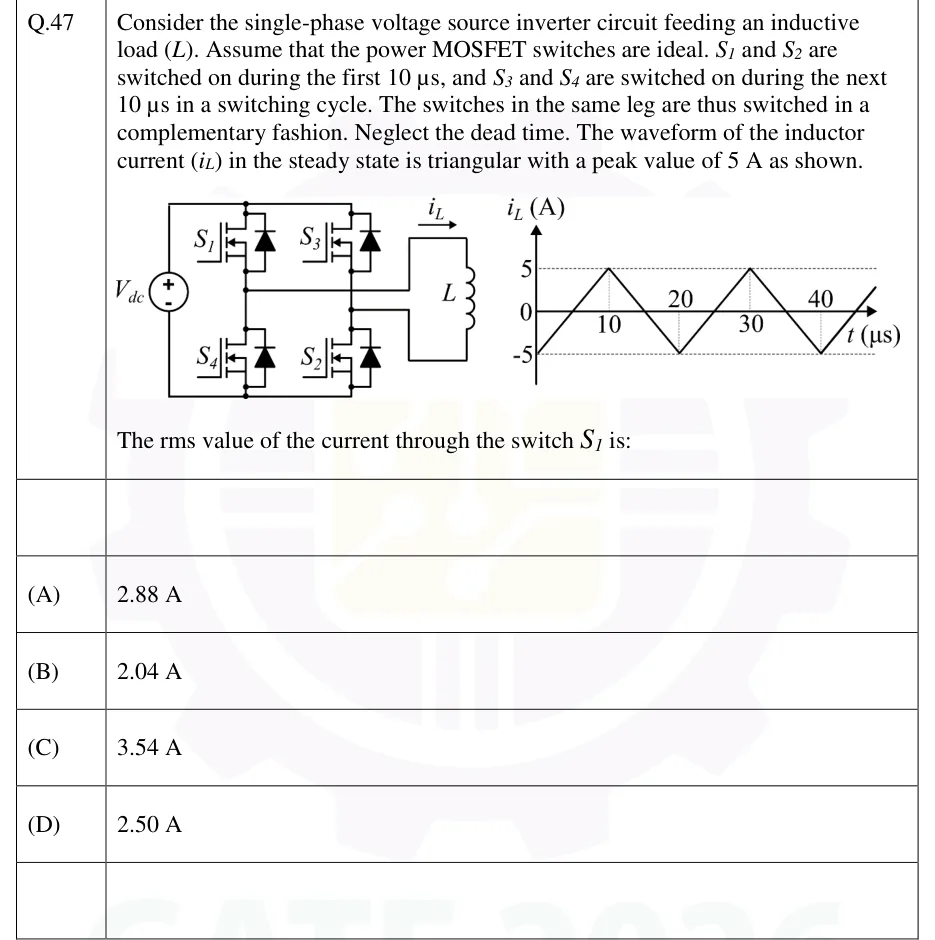
GATE 2026 EE question 47: Left: single-phase full bridge fed by a DC source V_dc (+ at top).Tap to open full size
Figure from the GATE 2026 EE paper. It is part of the question.
Figure description

Left: single-phase full bridge fed by a DC source V_dc (+ at top). Left leg has S1 (top) and S4 (bottom); right leg has S3 (top) and S2 (bottom). Each switch is a power MOSFET with an anti-parallel body diode. The inductive load L is connected between the midpoints of the two legs, with i_L marked as flowing from the left leg midpoint towards L. Right: plot of i_L (A) versus t (µs): a symmetric triangular wave starting at 0 at t = 0, peaks of +5 A, troughs of -5 A, dotted levels at +5 and -5, time marks at 10, 20, 30, 40 µs, so the period is 20 µs.

  1. (A)

    2.88 A

  2. (B)

    2.04 A

  3. (C)

    3.54 A

  4. (D)

    2.50 A

Answer and solution
GATE 2026 EE Q.47: answer and solution

GATE 2025 EE Q.46

GATE 2025 · EEQ.46 · 2 marks · MCQ

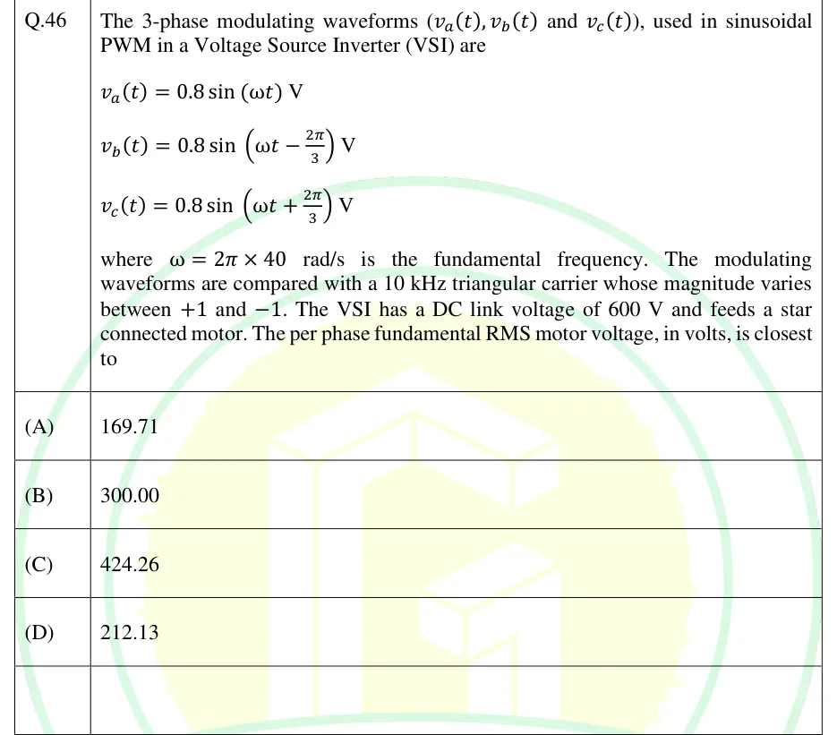
The 3-phase modulating waveforms ( and ), used in sinusoidal PWM in a Voltage Source Inverter (VSI) are V, V, V, where rad/s is the fundamental frequency. The modulating waveforms are compared with a 10 kHz triangular carrier whose magnitude varies between +1 and -1. The VSI has a DC link voltage of 600 V and feeds a star connected motor. The per phase fundamental RMS motor voltage, in volts, is closest to

  1. (A)

    169.71

  2. (B)

    300.00

  3. (C)

    424.26

  4. (D)

    212.13

Answer and solution
See the question in the paper
GATE 2025 EE Q.46: answer and solution

GATE 2024 EE Q.63

GATE 2024 · EEQ.63 · 2 marks · NAT

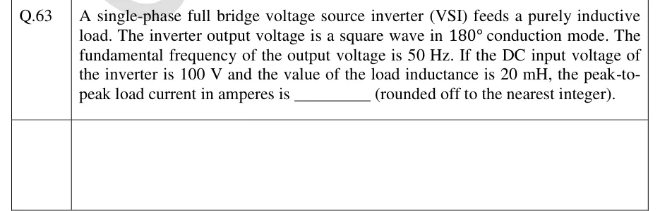
A single-phase full bridge voltage source inverter (VSI) feeds a purely inductive load. The inverter output voltage is a square wave in 180° conduction mode. The fundamental frequency of the output voltage is 50 Hz. If the DC input voltage of the inverter is 100 V and the value of the load inductance is 20 mH, the peak-to-peak load current in amperes is ______ (rounded off to the nearest integer).

Answer and solution
See the question in the paper
GATE 2024 EE Q.63: answer and solution

GATE 2022 EE Q.58

GATE 2022 · EEQ.58 · 2 marks · NAT

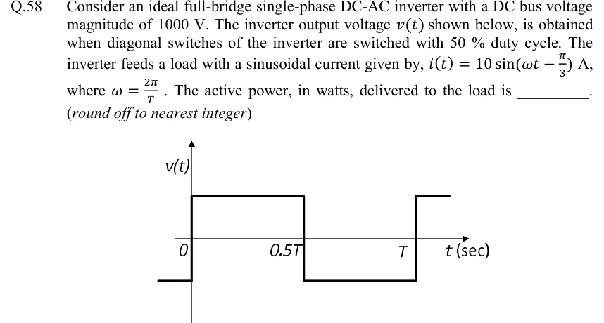
Consider an ideal full-bridge single-phase DC-AC inverter with a DC bus voltage magnitude of 1000 V. The inverter output voltage shown below, is obtained when diagonal switches of the inverter are switched with 50 % duty cycle. The inverter feeds a load with a sinusoidal current given by, A, where . The active power, in watts, delivered to the load is ______. (round off to nearest integer)

GATE 2022 EE question 58: Plot of v(t) against t (sec).Tap to open full size
Figure from the GATE 2022 EE paper. It is part of the question.
Figure description

Plot of v(t) against t (sec). Vertical axis v(t), horizontal axis t with marked instants 0, 0.5T and T. The waveform is a square wave: for t < 0 it sits at the negative level, jumps up at t = 0 to the positive level, stays positive until t = 0.5T, drops to the negative level from 0.5T to T, and jumps up again at t = T. Levels are +1000 V and -1000 V (the DC bus magnitude), so the waveform is symmetric about zero with a 50 % duty cycle.

Answer and solution
GATE 2022 EE Q.58: answer and solution

GATE 2022 EE Q.60

GATE 2022 · EEQ.60 · 2 marks · NAT

A 3-phase grid-connected voltage source converter with DC link voltage of 1000 V is switched using sinusoidal Pulse Width Modulation (PWM) technique. If the grid phase current is 10 A and the 3-phase complex power supplied by the converter is given by (−4000 − j3000) VA, then the modulation index used in sinusoidal PWM is ___________. (round off to two decimal places)

Answer and solution
See the question in the paper
GATE 2022 EE Q.60: answer and solution

GATE 2020 EE Q.22

GATE 2020 · EEQ.22 · 1 mark · NAT

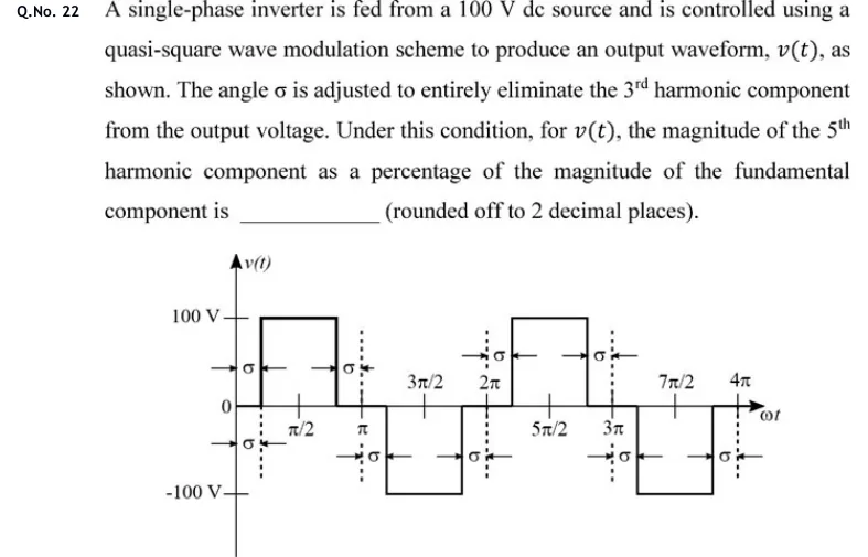
A single-phase inverter is fed from a 100 V dc source and is controlled using a quasi-square wave modulation scheme to produce an output waveform, v(t), as shown. The angle σ is adjusted to entirely eliminate the 3rd harmonic component from the output voltage. Under this condition, for v(t), the magnitude of the 5th harmonic component as a percentage of the magnitude of the fundamental component is ______ (rounded off to 2 decimal places).

GATE 2020 EE question 22: Plot of v(t) versus ωt with vertical axis marked +100 V, 0 and -100 V, and horizontal axis marked π/2, π, 3π/2, 2π, 5π/2…Tap to open full size
Figure from the GATE 2020 EE paper. It is part of the question.
Figure description

Plot of v(t) versus ωt with vertical axis marked +100 V, 0 and -100 V, and horizontal axis marked π/2, π, 3π/2, 2π, 5π/2, 3π, 7π/2, 4π. The wave is a quasi-square wave. It is at 0 for an angle σ at the start, then +100 V from ωt = σ to ωt = π − σ, then 0 for an angle σ on each side of π. It is then -100 V from ωt = π + σ to ωt = 2π − σ, then 0 for an angle σ on each side of 2π. The pattern repeats: +100 V from 2π + σ to 3π − σ, and -100 V from 3π + σ to 4π − σ. The zero intervals of width σ are marked with arrows and σ labels. The wave is odd-symmetric and quarter-wave symmetric about π/2.

Answer and solution
GATE 2020 EE Q.22: answer and solution

PRACTICE

7 questions to test yourself

PRACTICE 11 mark · MCQ

A single-phase full-bridge inverter operates in square-wave mode from a 200 V dc source. The rms value of the fundamental component of the output voltage is closest to:

  1. (A)

    90 V

  2. (B)

    141.4 V

  3. (C)

    180 V

  4. (D)

    200 V

Answer and solution

Answer: (C)

  1. Fundamental peak is V.

  2. RMS is V, that is .

PRACTICE 22 marks · NAT

A single-phase half-bridge inverter has a total dc input of 300 V (two equal halves of 150 V) and produces a square-wave output. Find the rms value of the third harmonic of the output voltage, in volts.

Answer and solution

Answer: (accepted range )

  1. Output amplitude is V.

  2. Peak of the nth harmonic is ; for it is V.

  3. RMS is V.

PRACTICE 32 marks · NAT

A three-phase SPWM inverter with sinusoidal references (no third-harmonic injection) operates in the linear region from a 540 V dc bus with amplitude modulation ratio 0.8. Find the rms value of the fundamental line-to-line voltage, in volts.

Answer and solution

Answer: (accepted range )

  1. Each leg's fundamental has peak V, rms V.

  2. Line: V, that is .

PRACTICE 41 mark · MCQ

An incremental shaft encoder gives 1024 pulses per revolution on each of channels A and B. With 4x decoding the counter increases by 2048 in 10 ms. The shaft speed is:

  1. (A)

    1500 rpm

  2. (B)

    3000 rpm

  3. (C)

    6000 rpm

  4. (D)

    12000 rpm

Answer and solution

Answer: (B)

  1. Counts per revolution with 4x decoding = 4 × 1024 = 4096.

  2. Revolutions in 10 ms = 2048/4096 = 0.5, so the speed is 50 rev/s = 3000 rpm.

PRACTICE 52 marks · NAT

A three-phase bridge inverter operates with 120° conduction from a 600 V dc source and supplies a balanced star-connected resistive load. Find the rms value of the fundamental component of the line-to-line voltage, in volts.

Answer and solution

Answer: (accepted range )

  1. The phase voltage is a quasi-square wave of amplitude V and width 120°.

  2. Its fundamental peak is V, so its rms is V.

  3. Line fundamental rms: V, that is .

PRACTICE 61 mark · MCQ

A single-phase full-bridge inverter produces a quasi-square output: for a width centred in each positive half-cycle, zero elsewhere, and the mirror image in the negative half-cycle. Which value of removes the 5th harmonic from the output?

  1. (A)

    36°

  2. (B)

    72°

  3. (C)

    90°

  4. (D)

    120°

Answer and solution

Answer: (B)

  1. The nth harmonic peak is proportional to .

  2. For it is zero when , that is or .

  3. Check the others: 36° gives , 90° gives , and 120° gives . Only 72° works.

PRACTICE 72 marks · MSQ

A three-phase bridge inverter with 180° conduction, fed from a dc voltage , supplies a balanced star-connected resistive load. Which statements are correct?

  1. (A)

    The line voltage contains no triplen harmonics.

  2. (B)

    The rms phase voltage is .

  3. (C)

    The rms line voltage is .

  4. (D)

    The lowest-order harmonic in the phase voltage is the 3rd.

Answer and solution

Answer: (A), (C)

  1. Phase voltage levels are and , giving rms , not , so B is false.

  2. The line voltage is a 120°-wide quasi-square wave of amplitude , with rms , so C is true.

  3. Harmonics are of order in both, so the lowest is the 5th and triplens are absent: A is true, D is false.

OFFICIAL GATE 2027 SYLLABUS WORDING

Copied from the GATE 2027 syllabus; see all 2027 syllabi.

GATE EE

Single-phase and three-phase voltage and current source inverters, sinusoidal pulse width modulation

GATE IN

single phase inverters; rotor position and speed sensing, current sensing, pulse width modulation (PWM) control

Preparing in Kolkata? IAE Academy's course for GATE EE or GATE IN.