IAE Academy

GATE EC · EE · IN

Modelling, block diagrams and signal flow graphs

This topic covers how a physical system (a circuit, a mass-spring-damper, a motor, a sensor loop) becomes a transfer function, and how a network of such transfer functions is reduced to one closed-loop transfer function using block-diagram algebra or Mason's gain formula. It also explains what negative feedback does to gain, sensitivity, disturbances, noise and bandwidth. Later Control Systems work starts from the transfer functions derived here. Time response and steady-state error use the closed-loop or error transfer function. Root locus, Bode and Nyquist analysis use the loop transfer function (the product of all the gains around the loop). An error at this stage therefore carries through to every answer that follows.

10 previous-year questions · 10 solved · 7 practice questions

1. Open loop, closed loop and the feedback principle

An open-loop system applies a control action that does not depend on the output. Examples are a heater run on a timer, or a stepper motor driven by a fixed pulse count. If the plant drifts or a disturbance arrives, nothing corrects it. A closed-loop (feedback) system measures the output with a sensor and compares that measurement with the reference. The difference (the actuating or error signal) drives the plant. With negative feedback the measured signal is subtracted at the comparator; with positive feedback it is added.

The standard single loop works like this. The reference enters a comparator. The forward path (controller, actuator and plant in cascade) produces the output . The feedback path (the sensor or transducer) returns to the comparator, and the actuating signal is . The product of everything around the loop, , is the open-loop or loop transfer function. Root locus, Bode and Nyquist analysis all work on .

CLOSED-LOOP TRANSFER FUNCTION (NEGATIVE FEEDBACK)

Here the feedback signal is subtracted at the comparator. The characteristic equation is . After clearing fractions, its roots are the closed-loop poles.

CLOSED-LOOP TRANSFER FUNCTION (POSITIVE FEEDBACK)

Here the feedback signal is added at the comparator. The characteristic equation is .

ACTUATING-SIGNAL TRANSFER FUNCTION

This uses with negative feedback. For unity feedback (), is the true error . With non-unity , the actuating signal is not the reference-minus-output error.

Role of sensing. A loop can only regulate what its sensor reports. With high loop gain (), . The closed-loop gain is then set almost entirely by the sensor, and the forward-path hardware barely matters. The flip side is that sensor errors are not corrected. A 2% gain error in becomes roughly a 2% error in the output. Sensor noise enters the comparator at the same point as the reference, so the loop passes it to the output instead of rejecting it. The sensor therefore has to be at least as accurate, and at least as quiet, as the output accuracy you need.

Aspect

Open loop

Closed loop (negative feedback)

Control action depends on the output?

No

Yes, through the sensor

Overall gain

, reduced by the factor

Sensitivity to a change in

(full)

Disturbance entering the forward path

Passes uncorrected

Reduced by the factor compared with open loop (Section 4)

Accuracy set by

Calibration of every block

Mainly the sensor and the reference

Stability

A stable plant stays stable

Can stabilise an unstable plant or destabilise a stable one

Bandwidth

That of the plant

Generally increased

Cost and complexity

Lower

Higher (sensor and comparator needed)

Component

Role in the loop

Linear model

Potentiometer pair

Error detector for angular position

, with in V/rad

Synchro transmitter + control transformer

AC error detector for angular position

The error voltage is an amplitude-modulated (suppressed-carrier) AC signal whose amplitude is near null

Tachogenerator

Speed sensor, used for rate (derivative) feedback

, so

DC servomotor

Actuator

Armature-controlled and field-controlled models are in Section 3

Two-phase AC servomotor

Actuator for low-power instrument servos

, from the linearised torque-speed curve; its negative slope acts as damping

Gear train

Matches motor speed and torque to the load

(Section 3)

Amplifier / controller

Shapes the actuating signal

A gain or a compensator

EXAM TIP

In a question, 'open-loop transfer function' normally means the loop gain , not the forward path alone. The two are the same only when . Check which one the question gives before you form .

2. Transfer function, poles and zeros

The transfer function of a linear time-invariant (LTI) system is the Laplace transform of the output divided by the Laplace transform of the input, with all initial conditions zero. It depends only on the system, not on the input applied, and it equals the Laplace transform of the impulse response. It is not defined for nonlinear or time-varying systems. It describes only the input-output relationship: a mode cancelled between numerator and denominator is still physically present, even though the transfer function no longer shows it.

DEFINITION OF THE TRANSFER FUNCTION

Applies to LTI systems only. is the unit-impulse response.

TRANSFER FUNCTION FROM A LINEAR DIFFERENTIAL EQUATION

With all initial conditions zero, each becomes . The denominator polynomial set to zero is the characteristic equation.

POLE-ZERO (ROOT-LOCUS) FORM

The zeros are the values of that make . The poles are the roots of the denominator, where . is the order of the system. is proper if and strictly proper if ; physical systems are proper.

TIME-CONSTANT (BODE) FORM

is the number of poles at the origin. For the loop , is the type. With , is the DC gain, which is the steady-state output per unit step if the system is stable.

Setting the denominator to zero gives the characteristic equation. Its roots, the poles, fix the natural (transient) modes. A simple real pole at contributes . A real pole repeated times contributes . A complex pair contributes . Zeros create no modes of their own; they only change how strongly each mode is excited. A proper rational transfer function, with common factors cancelled, is BIBO stable if and only if every pole lies strictly in the left half of the s-plane. If a right-half-plane pole is cancelled by a zero, the transfer function looks stable, but the physical system is still internally unstable. For a closed loop , the poles are the roots of , not the poles of . The closed-loop zeros are the zeros of together with the poles of , unless a common factor cancels.

EXAM TIP

Read gains carefully. has pole-zero gain , but its DC gain is . Root locus uses from the pole-zero form. Bode plots and steady-state error use the time-constant form, here .

EXAM TIP

Order and type are different counts. Order is the number of poles (the degree of the denominator) of the transfer function in question. Type is the number of poles at of the open-loop . For example, is third order and type 1.

EXAM TIP

If you are given the unit-step response of an LTI system that starts at rest, then and the impulse response is (this includes an impulse if jumps at ). Example: for gives , so .

3. Mathematical modelling: electrical, mechanical and electromechanical systems

To model a physical system:

1. Choose variables: a displacement for every independently moving mass or inertia, and a current for every mesh or a voltage for every node.
2. Write the element laws.
3. Apply Newton's second law to each mass: the net applied force equals mass times acceleration. D'Alembert's principle is the same law written as a force balance that includes the inertial force . For circuits, apply KVL or KCL instead.
4. Take Laplace transforms with zero initial conditions.
5. Eliminate the internal variables to get output/input.

Element

Law

Laplace form (zero initial conditions)

Mass

Translational damper

Translational spring

Moment of inertia

Rotational damper

Torsional spring

Resistor

Inductor

Capacitor

Translational

Rotational

Force-voltage (F-V, loop)

Force-current (F-I, node)

Force

Torque

Voltage

Current

Mass

Inertia

Inductance

Capacitance

Damping

Damping

Resistance

Conductance

Stiffness

Stiffness

Elastance

Reciprocal inductance

Displacement

Angle

Charge

Flux linkage

Velocity

Angular velocity

Current

Voltage

Elements sharing one velocity

Elements sharing one angular velocity

Carry the same current: in series, in one mesh

Share the same voltage: in parallel, across one node

MASS-SPRING-DAMPER

Derived from . The natural frequency is , the damping ratio is , and the DC gain (static compliance) is .

ANALOGOUS CIRCUIT EQUATIONS

These are the mass-spring-damper equation rewritten with the analogues. F-V gives a series RLC driven by a voltage source, with . F-I gives a parallel RLC driven by a current source, with node voltage velocity.

SERIES RLC, OUTPUT ACROSS C

Series , and driven by . Here and .

INVERTING OP-AMP STAGE

This assumes an ideal op-amp (infinite open-loop gain, zero input current) with its non-inverting input grounded. is in series with the input and connects the output to the inverting input. With and the stage is an integrator, . A second inverting stage restores the sign. An ideal op-amp has zero output impedance, so cascaded stages do not load each other.

ARMATURE-CONTROLLED DC MOTOR

Motor torque is and back emf is , with and referred to the motor shaft. The back emf is a built-in negative velocity feedback. In SI units, numerically. For speed output, drop the factor : . With a load torque opposing the motor, superposition gives .

DC MOTOR SPEED WITH NEGLIGIBLE ARMATURE INDUCTANCE

Valid when . is the steady-state speed per volt. The inertia affects only the time constant, not the final speed.

FIELD-CONTROLLED DC MOTOR

The armature current is held constant, so the torque is , where includes that constant armature current. Back emf does not affect the torque, so, unlike the armature-controlled motor, there is no inherent velocity feedback.

GEAR TRAIN AND REFLECTED LOAD

Gear 1 (motor side) has teeth and gear 2 (load side) has . To refer a load-side , or stiffness to the motor side, multiply by . For ideal lossless gears the torque scales as , so a load torque referred to the motor side becomes .

EXAM TIP

The F-I analogy keeps the mechanical layout. Every point with its own displacement (every mass) becomes one electrical node, and each mass becomes a capacitor from that node to ground. A spring or damper between two points becomes an inductor or a resistor between the corresponding nodes. A spring or damper attached to a fixed wall goes from its node to ground, because the wall is the reference node. An applied force becomes a current source into its node. The F-V analogy puts the same elements into meshes, so its circuit is the dual. Mass is analogous to inductance in F-V and to capacitance in F-I; do not mix the two columns.

WORKED EXAMPLE

Mass is driven by a force and is joined to mass by a spring of stiffness . Mass is connected to a fixed wall by a viscous damper . Both masses slide without friction. Find , where is the displacement of , and describe the force-current analogue.

Solution
  1. Newton's law on : . With zero initial conditions: .

  2. On : , which gives .

  3. From the second equation, . Substituting into the first: .

  4. Expand; the terms cancel: .

  5. Physical check: only the damper ties the masses to the wall, so a constant force produces a steady velocity, not a steady position. The pole at shows this. The cubic factor has all its roots in the left half-plane for any positive values: all coefficients are positive, and . So the final value theorem applies to the velocity . It gives , which is the speed at which the damper force balances the applied force.

  6. Force-current analogue: node 1 carries the velocity of and node 2 the velocity of . A current source feeds node 1. A capacitor runs from node 1 to ground. An inductor with joins nodes 1 and 2. A capacitor runs from node 2 to ground. A resistor with conductance runs from node 2 to ground, because the wall is ground.

Answer: , and a constant force gives a final velocity of .

4. Effects of feedback: gain, sensitivity, disturbance, noise and bandwidth

Split the forward path as . A disturbance is added between and . Sensor noise is added to the sensor output, so the comparator forms . By superposition, the output is:

OUTPUT WITH REFERENCE, DISTURBANCE AND SENSOR NOISE

Negative feedback. The noise term has the same transfer function as the reference, with a minus sign, so no amount of loop gain can separate the two.

SENSITIVITY (DEFINITION)

The fractional change in per fractional change in the parameter , equal to . It is valid for small changes. For a large change, compute before and after instead.

CLOSED-LOOP SENSITIVITY TO G AND TO H

For negative feedback, . An open loop () has . When , but , so a feedback-path error reaches the output almost one-for-one. For the frequency-dependent sensitivity, evaluate at .

CHAIN RULE FOR A PARAMETER INSIDE G

For any parameter inside . If , then , so .

DISTURBANCE TRANSFER FUNCTION

For a disturbance entering after . Compared with open loop, where , feedback reduces the disturbance's effect by the factor . In the high-gain limit, only the gain upstream of the disturbance point (and ) sets the residual effect ; raising does not reduce it. For a disturbance added directly at the output, .

GAIN-BANDWIDTH TRADE (FIRST-ORDER PLANT)

Plant with a constant negative-feedback gain (use for unity feedback). The DC gain falls by the factor . The bandwidth rises from to rad/s, and the time constant shrinks by the same factor. The gain-bandwidth product stays .

What negative feedback does (at frequencies where |1 + GH| > 1)

  1. Reduces the overall gain by the factor . This is the price paid for every benefit below.

  2. Reduces the sensitivity to forward-path variations by the same factor.

  3. Increases the bandwidth and speeds up the response (by in the first-order case).

  4. Reduces the effect of disturbances that enter the forward path.

  5. Does NOT reduce the sensitivity to the feedback element, and does NOT reject sensor noise.

  6. Moves the closed-loop poles, so it can stabilise an unstable plant, or destabilise a stable one if the loop gain or phase lag is too large.

  7. Positive feedback, , has . For real , it raises both the gain and the sensitivity above their open-loop values. It is used in regenerative circuits and oscillators, not for regulation.

WORKED EXAMPLE

An amplifier has open-loop gain and is placed in a negative-feedback loop with constant feedback gain . (a) Find the closed-loop DC gain and the sensitivity of that DC gain to . (b) The amplifier's DC gain drops by 20%. Estimate the change in closed-loop DC gain from the sensitivity, then compute it exactly. (c) Compare the open-loop and closed-loop bandwidths.

Solution
  1. DC loop gain: . So .

  2. .

  3. Estimate: .

  4. Exact: with , , a change of . The sensitivity estimate is a small-change (first-order) approximation. Both results show a 20% drift reduced to well under 1%.

  5. Closed loop: .

  6. Bandwidth: 100 rad/s open loop and 5000 rad/s closed loop, larger by the factor . Gain times bandwidth is rad/s in both cases, so it is unchanged.

Answer: (a) and . (b) About estimated and exact (). (c) The bandwidth rises from 100 rad/s to 5000 rad/s, and the gain-bandwidth product stays rad/s.

EXAM TIP

The benefits of negative feedback hold only at frequencies where . Where , which can happen near gain crossover in a lightly damped loop, negative feedback increases sensitivity and amplifies disturbances instead.

EXAM TIP

Sensitivity is a derivative, so it is accurate only for small changes. In a '20% change' question with options close together, compute exactly at the new parameter value rather than using .

5. Block diagram reduction

A block diagram shows signals (arrows) and transfer functions (blocks). A block multiplies the signal passing through it. A summing point adds or subtracts its incoming signals, each with its own sign. A takeoff (pickoff) point copies a signal to several destinations without changing it. Reduction replaces part of the diagram with an equivalent that gives the same outputs for the same inputs.

Operation

Original

Equivalent

Cascade (series) blocks

One block

Parallel blocks

and fed by the same , outputs summed with signs

One block

Eliminate a feedback loop

Forward path , feedback path

( for negative feedback)

Move a summing point downstream past

enters

: insert in the branch

Move a summing point upstream past

: insert in the branch

Move a takeoff point downstream past

tapped before

Tap after and insert in the tapped branch

Move a takeoff point upstream past

tapped after

Tap before and insert in the tapped branch

Adjacent summing points

Two summing points in a row

Interchange or merge freely

Adjacent takeoff points

Two takeoff points on one line

Interchange freely

Non-unity to unity feedback

with feedback

in cascade with a unity loop around

Reduction procedure

  1. With several inputs, find the output for one input at a time with the others set to zero (superposition), then add the results. If the input you keep enters a summing point with a minus sign, carry that sign as a gain of .

  2. Combine every cascade and every parallel group.

  3. Eliminate inner loops that do not overlap other loops, innermost first.

  4. Where loops overlap, move a summing point or takeoff point past a block to separate them, inserting the compensating block.

  5. Repeat until a single block remains.

  6. Cross-check: once the result is written in terms of the individual block gains, its denominator should equal from Mason's formula (Section 6), unless a common factor has cancelled.

EQUIVALENT UNITY-FEEDBACK FORWARD PATH

A unity negative-feedback loop around has the same closed-loop transfer function . Use it when a steady-state-error formula assumes unity feedback, so that is the true error.

WORKED EXAMPLE

A block diagram has the forward chain . and are summing points, and is a takeoff point on the output of . forms : the signal at is fed back through , there is unity feedback from , and both are subtracted. forms (output of ) . Find by block-diagram reduction, and check it with Mason's formula.

Solution
  1. The loop (through and ) and the loop (through and ) overlap. Each contains a block the other lacks, so neither can be eliminated first.

  2. Move takeoff point downstream past . The fed-back signal must stay , so insert : the branch from to now has gain .

  3. The loop is now self-contained. with feedback reduces to .

  4. At , two signals taken from are both subtracted: itself and . They are parallel feedback paths, so combine them into one feedback block .

  5. The forward path is now . Closing the loop: .

  6. Mason check: there is one forward path, . The loops are , and . All three pass through the output node of and through , so they touch each other and the forward path. Then and , which gives the same result.

  7. Special-case check: with every block and feedback gain equal to 1, the formula gives . Directly: , the output of is , the output of is , and , so .

Answer:

EXAM TIP

Rule for moving a point across a block: insert whatever keeps the moved signal unchanged. Moving a summing point downstream or a takeoff point upstream: insert . Moving a summing point upstream or a takeoff point downstream: insert .

EXAM TIP

A summing point and a takeoff point that sit next to each other cannot be swapped without a correction branch. After the swap, the tapped signal would include (or miss) the signal the summing point adds.

EXAM TIP

Multiplying cascaded transfer functions is valid only if the second stage does not load the first. Two identical RC low-pass sections connected directly do NOT give ; the correct result is . With a unity-gain buffer between the sections, the simple product is correct.

6. Signal flow graphs and Mason's gain formula

A signal flow graph (SFG) draws a set of linear equations as nodes (the variables) joined by directed branches (the gains). A node's value is the sum of all signals entering it; the branches leaving a node do not change its value. SFGs apply only to linear systems written as cause-and-effect equations of the form .

Terminology

  1. Source (input) node: only outgoing branches. Sink (output) node: only incoming branches. Mixed node: both.

  2. Any mixed node can be made an output by adding a unity-gain branch from it to a new sink node. A mixed node cannot be made an input node this way.

  3. Path: a sequence of connected branches followed in the branch direction, with no node visited twice.

  4. Forward path: a path from an input node to an output node. Its gain is the product of its branch gains.

  5. Loop: a closed path that starts and ends at the same node, with no other node visited twice. Its gain is the product of the branch gains around it, signs included.

  6. Self-loop: a branch from a node back to itself, gain . It counts as a loop (). Removing it divides every branch entering that node by .

  7. Non-touching: two loops, or a loop and a path, with no node in common.

Converting a block diagram to an SFG

  1. Make every input, every output, every summing-point output and every takeoff point a node.

  2. Each block becomes a branch carrying that transfer function. A direct connection becomes a branch of gain 1.

  3. Put the summing-point sign into the branch: a signal subtracted through becomes a branch of gain .

  4. A summing point followed immediately by a takeoff point can share one node. A takeoff point placed before a summing point on the same line must be a separate node, joined to the summing node by a unity branch. Otherwise the tapped signal wrongly includes what the summing point added.

MASON'S GAIN FORMULA

The gain from a source node to any other node. is the gain of the -th forward path. is the graph determinant. is recomputed with every loop that touches the -th forward path removed.

GRAPH DETERMINANT

The second sum runs over every pair of mutually non-touching loops, the third over every triple, and so on. Loop gains carry their own signs, so a negative-feedback loop () adds to . is the characteristic equation, and is the same for every input-output pair in a given graph.

GAIN BETWEEN TWO NON-INPUT NODES

Mason's formula applies only from a source node. For the ratio of two internal nodes, apply it from the input to each node and divide; cancels.

Mason procedure

  1. List every forward path and its gain .

  2. List every loop and its gain , with signs. Look for loops that pass through more than one feedback branch, and for loops created by feedforward branches that start at a non-source node.

  3. Find all pairs, triples, and so on of mutually non-touching loops.

  4. Form .

  5. For each forward path, remove every loop that shares even one node with it. What remains of is , which is often 1.

  6. Assemble , and check a special case if you can (for example, set one feedback gain to zero).

WORKED EXAMPLE

A signal flow graph has nodes (input) to (output) and these branch gains: , , , , , , , , and a feedforward branch . There are no other branches. Find .

Solution
  1. Forward paths: is , with . is , with .

  2. Loops: is , . is , . is , . The feedforward branch starts at the source node, so it creates no loop.

  3. Non-touching pairs: (nodes ) and (nodes ) share no node, so . touches both. There are no triples.

  4. .

  5. passes through every node from to , so it touches all loops and . uses . It touches and but not , so .

  6. .

  7. Check with node equations: and give . Then . Since , , so .

Answer: . In symbols, write for , for , for and for the feedforward branch . Write for , for and for , with the other branches unity. Then . With , , , , , and , this is .

EXAM TIP

Do not count the minus sign twice. If the feedback branch is drawn as , the loop gain is already , so . Writing gives the positive-feedback answer.

EXAM TIP

Sharing a single node counts as touching. A loop that meets a forward path at just one node, such as the first summing node, must be removed when you form .

EXAM TIP

If every loop touches every forward path, all and the answer is simply . Check for this first; it happens often in graphs drawn from block diagrams.

PREVIOUS-YEAR QUESTIONS

10 questions from the EC, EE and IN papers

Try each question first, then open the answer. We placed each question under a topic ourselves; the exam paper does not label topics.

See these papers in full: GATE ECE 2026 · GATE ECE 2025 · GATE ECE 2023 · GATE ECE 2018 · GATE EE 2024 · GATE EE 2023 · GATE EE 2020 · GATE IN 2022

GATE 2026 EC Q.19

GATE 2026 · ECQ.19 · 1 mark · MCQ

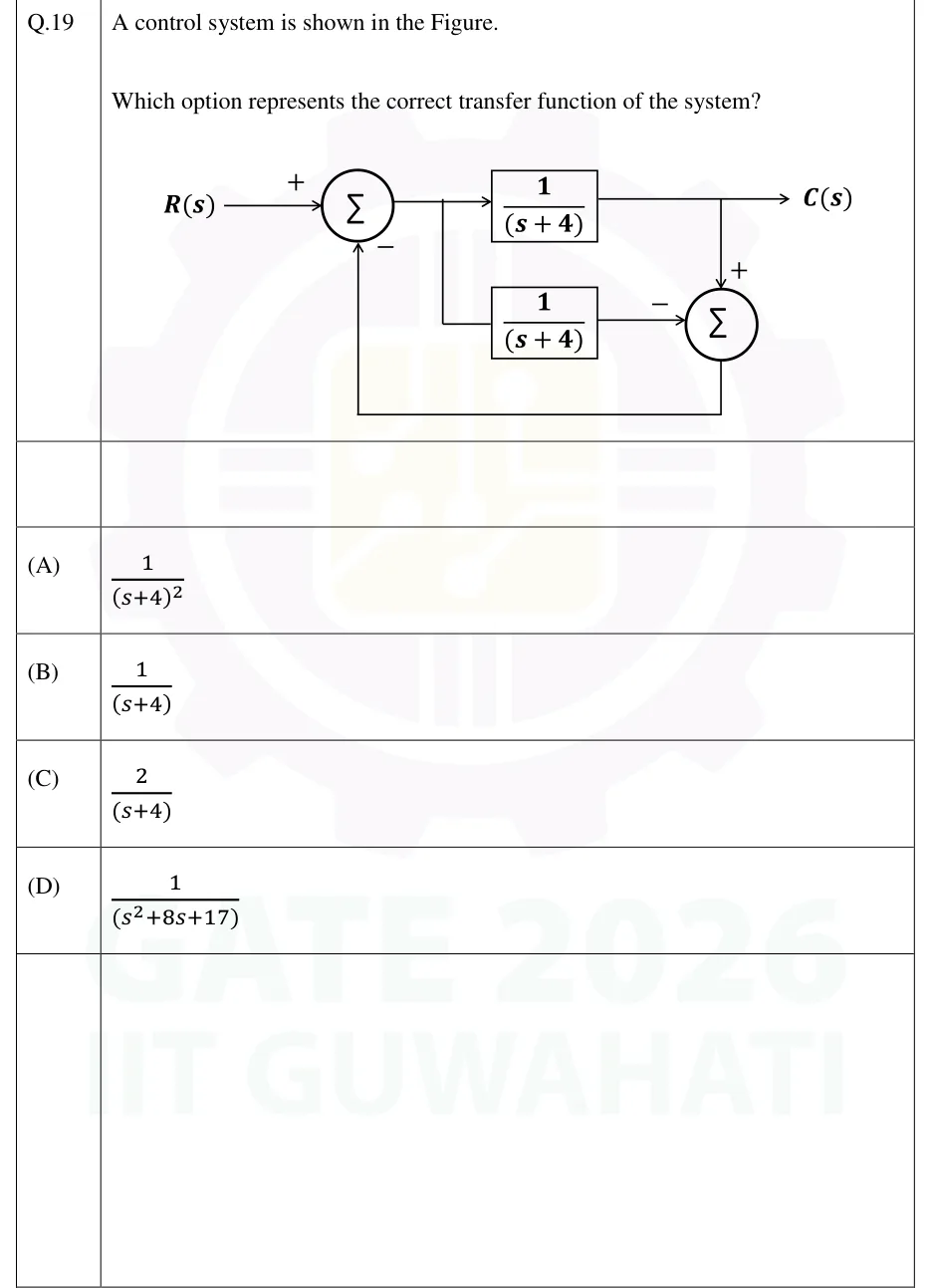
A control system is shown in the Figure.

Which option represents the correct transfer function of the system?

GATE 2026 EC question 19: Block diagram.Tap to open full size
Figure from the GATE 2026 EC paper. It is part of the question.
Figure description

Block diagram. R(s) enters summing junction 1 with sign +. The output of summing junction 1 (call it E(s)) goes right. A take-off point on that line sends E(s) into two blocks, each (1)/((s+4)): the top block sits on the main forward line, and the bottom block is fed by a branch that drops down from the take-off point. The output of the top block is C(s) (the system output, arrow to the right). A take-off point on the C(s) line goes down into summing junction 2 with sign +. The output of the bottom block enters summing junction 2 from the left with sign -. The output of summing junction 2 runs down, left along the bottom, and up into summing junction 1 with sign - (negative feedback).

  1. (A)

  2. (B)

  3. (C)

  4. (D)

Answer and solution
GATE 2026 EC Q.19: answer and solution

GATE 2025 EC Q.56

GATE 2025 · ECQ.56 · 2 marks · MSQ

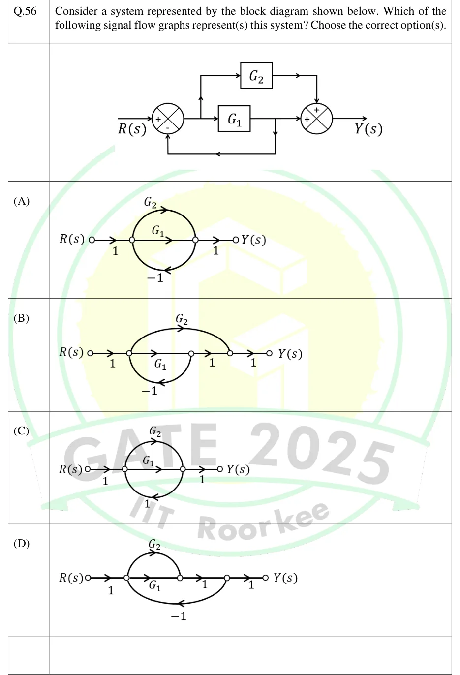
Consider a system represented by the block diagram shown below. Which of the following signal flow graphs represent(s) this system? Choose the correct option(s).

GATE 2025 EC question 56: Block diagram: R(s) enters the + input of summing junction 1.Tap to open full size
Figure from the GATE 2025 EC paper. It is part of the question.
Figure description

Block diagram: R(s) enters the + input of summing junction 1. Call the output of junction 1 E. It goes right into block G_1, and a take-off point on the line before G_1 sends it up into block G_2. The output of G_1 goes right into the left + input of summing junction 2. The output of G_2 goes right and then down into the top + input of summing junction 2. Junction 2's output is Y(s). A take-off point on the line between G_1 and junction 2 feeds a path that runs down, left along the bottom and up into the - input of junction 1. So the feedback carries only G_1's output; G_2's output is not fed back. Options A to D are signal flow graphs, each with input node R(s) and output node Y(s).

  1. (A)

    Figure: ; (straight branch); (upper arc); (lower arc, feedback); .

  2. (B)

    Figure: ; ; ; (upper arc that skips ); (lower arc, feedback); .

  3. (C)

    Figure: ; (straight branch); (upper arc); (lower arc, feedback gain ); .

  4. (D)

    Figure: ; (straight branch); (upper arc); ; (lower arc from back to , feedback); .

Answer and solution
GATE 2025 EC Q.56: answer and solution

GATE 2024 EE Q.20

GATE 2024 · EEQ.20 · 1 mark · MCQ

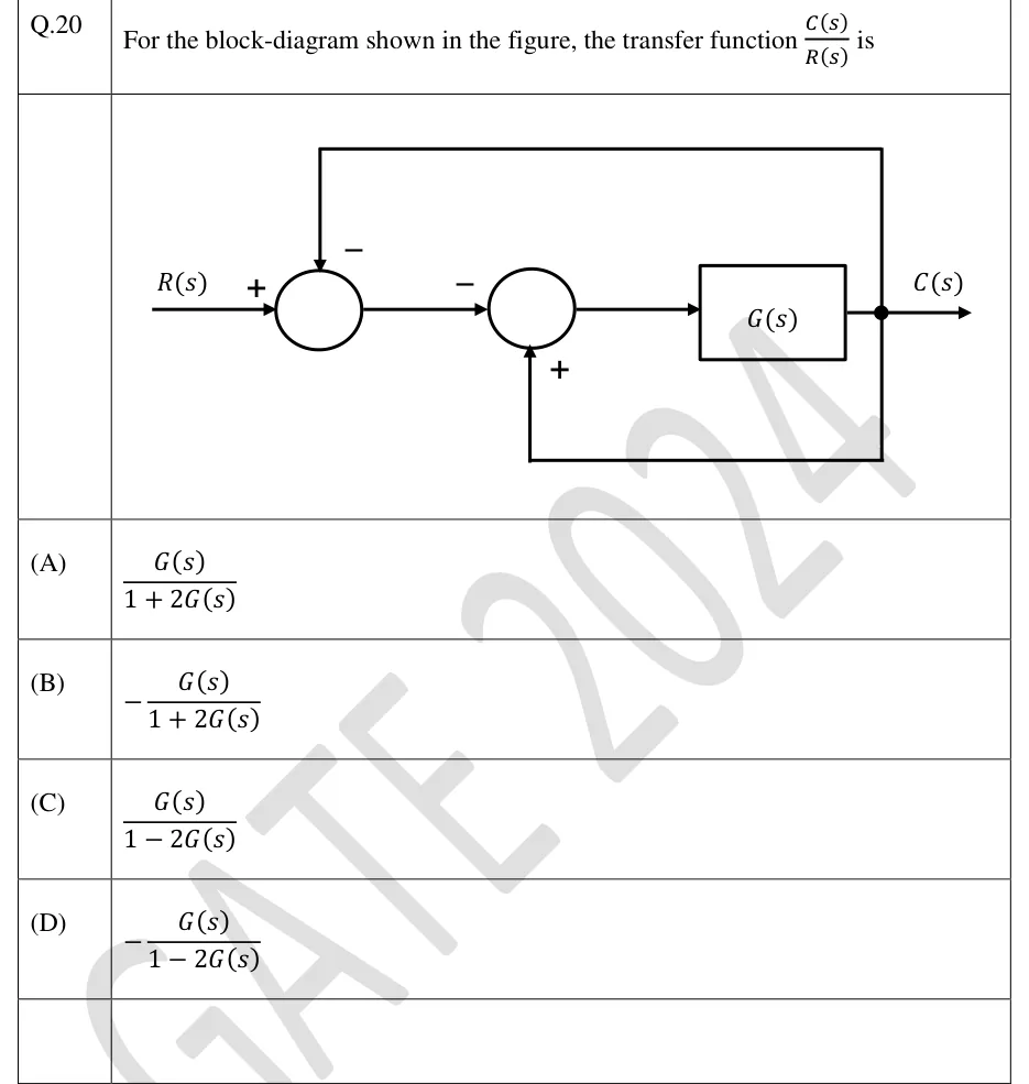
For the block-diagram shown in the figure, the transfer function is

GATE 2024 EE question 20: Two summing junctions in cascade followed by a single forward block G(s).Tap to open full size
Figure from the GATE 2024 EE paper. It is part of the question.
Figure description

Two summing junctions in cascade followed by a single forward block G(s). R(s) enters the first (left) summing junction with a + sign. The output of the first junction goes to the second summing junction, and that input carries a − sign. The output of the second junction feeds the block G(s), and the block's output is C(s). From a take-off point at C(s) there are two feedback paths. (1) The upper path goes back to the top of the first summing junction with a − sign, which is unity negative feedback. (2) The lower path goes back to the bottom of the second summing junction with a + sign, which is unity positive feedback. Neither feedback path has a block in it, so both have unity gain.

  1. (A)

  2. (B)

  3. (C)

  4. (D)

Answer and solution
GATE 2024 EE Q.20: answer and solution

GATE 2023 EC Q.42

GATE 2023 · ECQ.42 · 2 marks · MCQ

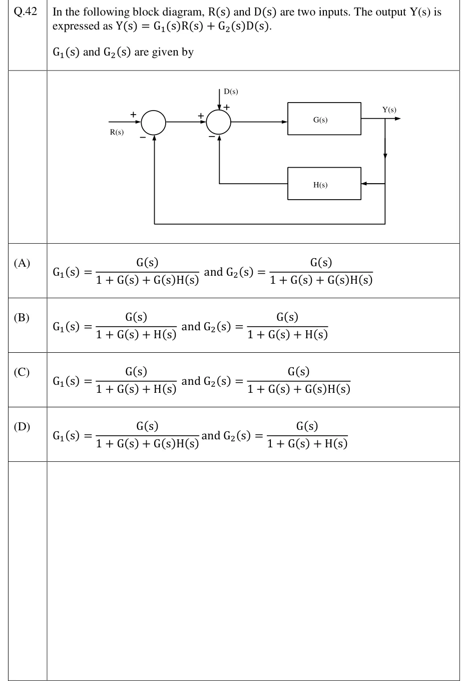
In the following block diagram, and are two inputs. The output is expressed as .

and are given by

GATE 2023 EC question 42: Two summing junctions in cascade, then a forward block G(s) whose output is Y(s).Tap to open full size
Figure from the GATE 2023 EC paper. It is part of the question.
Figure description

Two summing junctions in cascade, then a forward block G(s) whose output is Y(s). Summing junction 1: R(s) enters from the left with sign +; a unity feedback path taken straight from Y(s) enters from below with sign -. The output of junction 1 goes to summing junction 2 with sign +. Summing junction 2 also has D(s) entering from the top with sign +, and the output of block H(s) entering from below with sign -. H(s) is fed from Y(s): a branch drops down from the Y(s) take-off point into H(s), which is drawn on the lower path pointing back towards junction 2. The output of junction 2 feeds G(s); the output of G(s) is Y(s). So the loops are: inner loop G(s) with negative feedback H(s) into junction 2, and outer loop G(s) with negative unity feedback from Y(s) into junction 1.

  1. (A)

    and

  2. (B)

    and

  3. (C)

    and

  4. (D)

    and

Answer and solution
GATE 2023 EC Q.42: answer and solution

GATE 2023 EE Q.12

GATE 2023 · EEQ.12 · 1 mark · MCQ

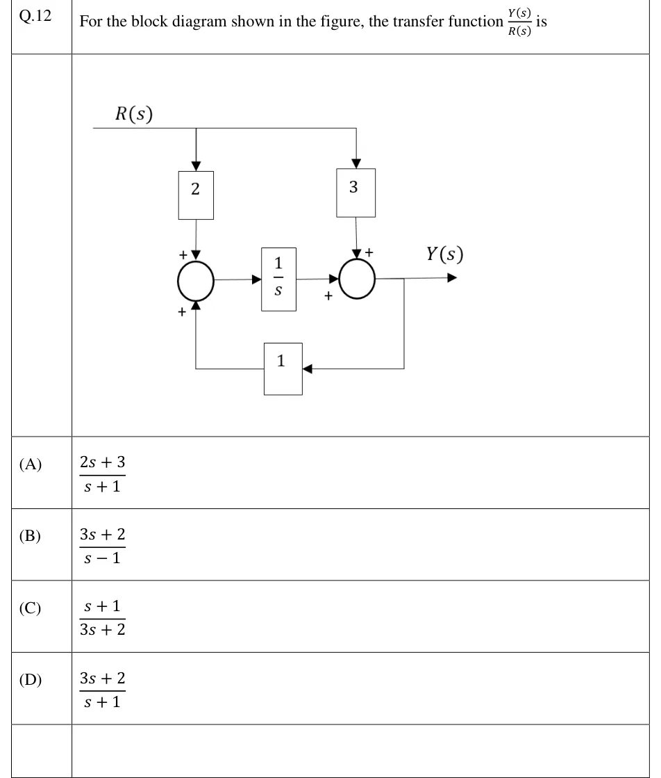
For the block diagram shown in the figure, the transfer function is

GATE 2023 EE question 12: Input R(s) enters from the left on a horizontal line that branches to two blocks.Tap to open full size
Figure from the GATE 2023 EE paper. It is part of the question.
Figure description

Input R(s) enters from the left on a horizontal line that branches to two blocks. Left branch: R(s) goes down into a block of gain 2, whose output enters summing junction 1 at the top with sign +. Right branch: R(s) goes down into a block of gain 3, whose output enters summing junction 2 at the top with sign +. The output of summing junction 1 goes right into a block 1/s; the output of 1/s enters summing junction 2 from the left with sign +. The output of summing junction 2 is Y(s). Y(s) is picked off and fed back leftward through a block of gain 1, entering summing junction 1 from below with sign + (positive feedback).

  1. (A)

  2. (B)

  3. (C)

  4. (D)

Answer and solution
GATE 2023 EE Q.12: answer and solution

GATE 2022 IN Q.37

GATE 2022 · INQ.37 · 2 marks · MCQ

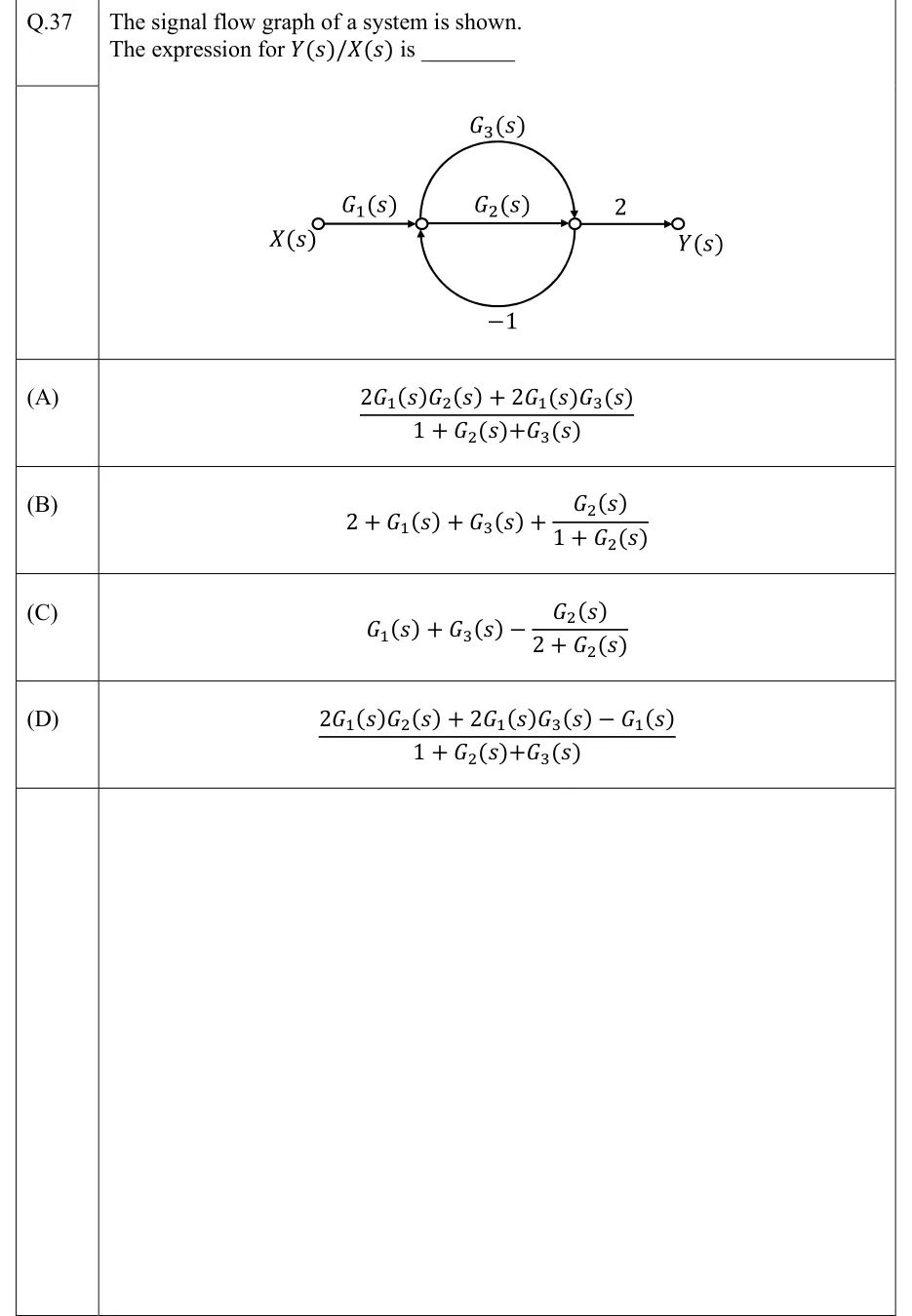
The signal flow graph of a system is shown. The expression for is ________

GATE 2022 IN question 37: Signal flow graph with four nodes in a row: input node X(s), node A, node B and output node Y(s).Tap to open full size
Figure from the GATE 2022 IN paper. It is part of the question.
Figure description

Signal flow graph with four nodes in a row: input node X(s), node A, node B and output node Y(s). A branch of gain G_1(s) runs from X(s) to A. A straight branch of gain G_2(s) runs from A to B. An upper semicircular arc of gain G_3(s) runs from A to B (arrowhead pointing down into B). A lower semicircular arc of gain -1 runs from B back to A (arrowhead pointing up into A). A branch of gain 2 runs from B to Y(s).

  1. (A)

  2. (B)

  3. (C)

  4. (D)

Answer and solution
GATE 2022 IN Q.37: answer and solution

GATE 2020 EE Q.13

GATE 2020 · EEQ.13 · 1 mark · MCQ

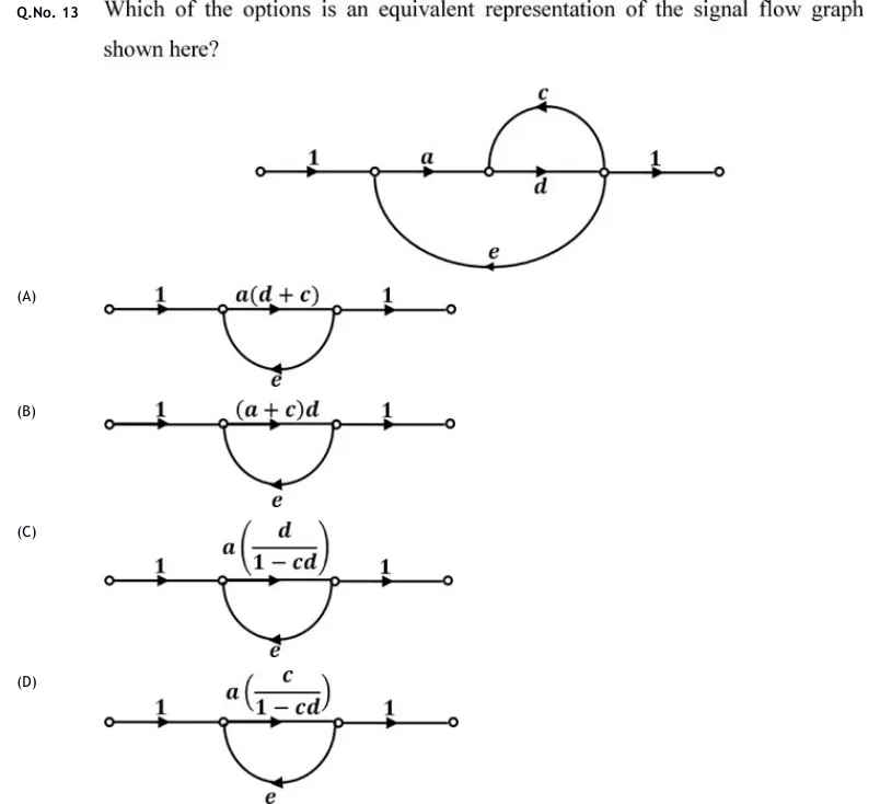
Which of the options is an equivalent representation of the signal flow graph shown here?

GATE 2020 EE question 13: Signal flow graph with five nodes on a horizontal line: input node x_0, then x_1, x_2, x_3, output node x_4.Tap to open full size
Figure from the GATE 2020 EE paper. It is part of the question.
Figure description

Signal flow graph with five nodes on a horizontal line: input node x_0, then x_1, x_2, x_3, output node x_4. Forward branches: x_0 → x_1 gain 1; x_1 → x_2 gain a; x_2 → x_3 gain d (straight branch); x_3 → x_4 gain 1. Branch c: an arc drawn above the line from x_3 back to x_2 (arrowhead at the top points left, so it is a feedback branch x_3 → x_2). Branch e: a large arc drawn below the line from x_3 back to x_1 (arrowhead at the bottom points left, so it is a feedback branch x_3 → x_1). Each option is a four-node graph: input 1 node P G node Q 1 output, with a branch e drawn below from Q back to P; the options differ only in the forward gain G.

  1. (A)

    Figure — input P Q output, feedback branch from Q to P

  2. (B)

    Figure — input P Q output, feedback branch from Q to P

  3. (C)

    Figure — input P Q output, feedback branch from Q to P

  4. (D)

    Figure — input P Q output, feedback branch from Q to P

Answer and solution
GATE 2020 EE Q.13: answer and solution

GATE 2018 EC Q.4

GATE 2018 · ECQ.4 · 1 mark · MCQ

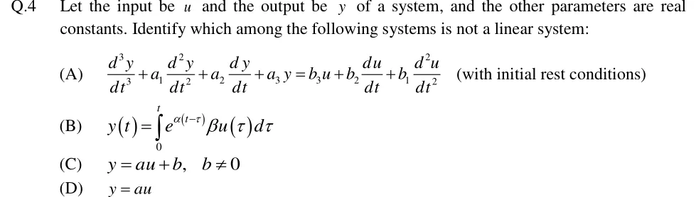
Let the input be and the output be of a system, and the other parameters are real constants. Identify which among the following systems is not a linear system:

  1. (A)

    (with initial rest conditions)

  2. (B)

  3. (C)

  4. (D)

Answer and solution
See the question in the paper
GATE 2018 EC Q.4: answer and solution

PRACTICE

7 questions to test yourself

PRACTICE 11 mark · NAT

A plant with nominal is placed in a unity negative-feedback loop. The sensitivity of the closed-loop DC gain to , , evaluated at the nominal value, is ______ (to two decimal places).

Answer and solution

Answer: (accepted range )

  1. , so the DC gain is .

  2. , so .

  3. At : . Check: .

PRACTICE 22 marks · MCQ

A signal flow graph has nodes (input) to and exactly these branches: : ; : ; : ; : ; : ; : ; : ; : . The transfer function is

  1. (A)

  2. (B)

  3. (C)

  4. (D)

Answer and solution

Answer: (B)

  1. Loops: on ; on ; on . Every feedback branch spans only one step, so any longer closed path would have to revisit a node. There are no other loops.

  2. Non-touching pairs: only and (nodes and ). and share ; and share .

  3. .

  4. Forward paths: passes through every node and touches all loops, so . runs and does not touch , so .

  5. . Check with every gain equal to 1: Mason gives , and solving the node equations directly also gives .

PRACTICE 32 marks · MSQ

A plant with and is in a unity negative-feedback loop. A disturbance is added directly to the plant output. Sensor noise is added to the measured output, so the comparator forms . Which of the following statements are correct?

  1. (A)

    The closed-loop DC gain from to is .

  2. (B)

    The closed-loop dB bandwidth from to is rad/s.

  3. (C)

    As , the steady-state output caused by a constant sensor noise tends to zero.

  4. (D)

    For a unit-step disturbance with , the steady-state output is .

Answer and solution

Answer: (A), (B), (D)

  1. , so .

  2. A: . Correct.

  3. B: has a single pole at , so the bandwidth is rad/s. Correct.

  4. C: , whose DC value tends to as . The noise reaches the output almost in full, and raising the gain makes it worse. Incorrect.

  5. D: . The loop is stable, so by the final value theorem the unit-step response settles at . Correct.

PRACTICE 42 marks · NAT

An armature-controlled DC motor has armature resistance , negligible armature inductance, torque constant N·m/A and back-emf constant V·s/rad. The total inertia is kg·m² and the viscous friction is N·m·s/rad, both referred to the motor shaft. There is no load torque. A constant 12 V is applied to the armature with the motor starting from rest. The steady-state speed, in rad/s, is ______ (to two decimal places).

Answer and solution

Answer: (accepted range )

  1. With : .

  2. DC gain (rad/s)/V.

  3. Steady-state speed rad/s.

  4. Physical check: armature current A, so the motor torque is N·m. This equals the friction torque N·m.

  5. sets only the time constant, s, and does not affect the final speed.

PRACTICE 52 marks · MCQ

In a block diagram, the reference enters a first summing point. Its other input is the output fed back through with a minus sign. The output of the first summing point drives . At a second summing point, the output of is added to a feedforward signal taken directly from . The output of the second summing point drives , whose output is . The transfer function is

  1. (A)

  2. (B)

  3. (C)

  4. (D)

Answer and solution

Answer: (C)

  1. Call the output of the first summing point . Then and .

  2. Substitute: , so .

  3. .

  4. Mason check: the forward paths are and . The only loop is . The feedforward branch starts at the source node , so it forms no loop, which rules out option B. Both forward paths pass through the second summing node and , which lie on the loop, so .

  5. Option A forgets that the feedforward signal also passes through . Option D treats the feedforward as a multiplying factor instead of adding it at the summing point.

PRACTICE 61 mark · NAT

A motor drives a load through an ideal gear pair. The motor-side gear has 20 teeth and the load-side gear has 100 teeth. The motor rotor inertia is 0.01 kg·m² and the load inertia is 1 kg·m²; the gear inertias are negligible. The total inertia referred to the motor shaft, in kg·m², is ______ (to two decimal places).

Answer and solution

Answer: (accepted range )

  1. Refer the load inertia to the motor shaft with the factor .

  2. kg·m².

  3. Energy check: the load turns at , so the total kinetic energy is .

PRACTICE 71 mark · MCQ

In the force-current analogy, the stiffness of a translational spring is analogous to

  1. (A)

    Capacitance

  2. (B)

    Inductance

  3. (C)

    Reciprocal of inductance,

  4. (D)

    Reciprocal of capacitance,

Answer and solution

Answer: (C)

  1. In the force-current analogy, force corresponds to current and velocity corresponds to voltage .

  2. Spring: . Inductor: .

  3. Matching term by term gives . Option D, , is the force-voltage answer, where is matched with .

OFFICIAL GATE 2027 SYLLABUS WORDING

Copied from the GATE 2027 syllabus; see all 2027 syllabi.

GATE EC

Basic control system components; Feedback principle; Transfer function; Block diagram representation; Signal flow graph

GATE EE

Mathematical modelling and representation of systems, Feedback principle, transfer function, Block diagrams and Signal flow graphs

GATE IN

Feedback principles, role of sensing in feedback, signal flow graphs

Preparing in Kolkata? IAE Academy's course for GATE ECE, GATE EE or GATE IN.