
IAE Academy

GATE 2025 EC Q.56: solution and answer

GATE 2025 · ECQ.56 · 2 marks · MSQ

Consider a system represented by the block diagram shown below. Which of the following signal flow graphs represent(s) this system? Choose the correct option(s).
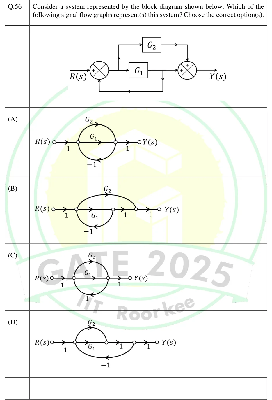
GATE 2025 EC question 56: Block diagram: R(s) enters the + input of summing junction 1.Tap to open full size
Figure from the GATE 2025 EC paper. It is part of the question.
Figure description

Block diagram: R(s) enters the + input of summing junction 1. Call the output of junction 1 E. It goes right into block G_1, and a take-off point on the line before G_1 sends it up into block G_2. The output of G_1 goes right into the left + input of summing junction 2. The output of G_2 goes right and then down into the top + input of summing junction 2. Junction 2's output is Y(s). A take-off point on the line between G_1 and junction 2 feeds a path that runs down, left along the bottom and up into the - input of junction 1. So the feedback carries only G_1's output; G_2's output is not fed back. Options A to D are signal flow graphs, each with input node R(s) and output node Y(s).

  1. (A)

    Figure: ; (straight branch); (upper arc); (lower arc, feedback); .

  2. (B)

    Figure: ; ; ; (upper arc that skips ); (lower arc, feedback); .

  3. (C)

    Figure: ; (straight branch); (upper arc); (lower arc, feedback gain ); .

  4. (D)

    Figure: ; (straight branch); (upper arc); ; (lower arc from back to , feedback); .

Answer and solution

ANSWER

Only signal flow graph (B) represents the system. The block diagram and graph B both give . Graphs A and D give , and C gives .

Official answer: BSource: Official answer key, GATE 2025 EC (IIT Roorkee)

  1. Block diagram. Let be the output of the first summer. The feedback path starts after and before the second summer, so it carries only . That gives , so .

  2. The second summer adds both branches: .

  3. So the target transfer function is The system has one loop, with gain . The branch is a feedforward path outside that loop.

  4. (A) The forward paths are and . The branch leaves , where and have already merged. That makes two loops, and . They share and , so they touch, and . Both forward paths touch both loops, so and . A is wrong.

  5. (B) The branch leaves , which carries only . joins later, at , and nothing leads from back into the graph, so the only loop is and . The forward paths (through ) and (through ) both pass through , so both touch the loop and . That gives , which matches. Node equations give the same result: , so , and .

  6. (C) The paths merge before the feedback node, as in A, but the feedback gain is . The loops are and , so and . C is wrong.

  7. (D) The feedback leaves , and , so the fed-back signal again includes 's output. The loops are and , as in A, so . D is wrong.

  8. Only graph B represents the block diagram. The answer is B.

KEY IDEA

In a signal flow graph, a feedback branch must start at a node that carries exactly the signal the block diagram feeds back. Here the feedback takes 's output before 's output is added. The graph therefore needs a node that holds alone, separate from a later node where joins. Only graph B has one, so its only loop is and stays a feedforward path.

WATCH OUT FOR

Treating the take-off point after and the second summing junction as one node. Graphs A and D do this. The fed-back signal then becomes , which adds a second loop and gives . A second slip is missing the sign change in C: a feedback branch turns the minus signs in into plus signs.

From the GATE 2025 EC paper. Every question of this paper · Download the full paper · All 10 Block diagrams & SFG questions, with notes

More Block diagrams & SFG questions