
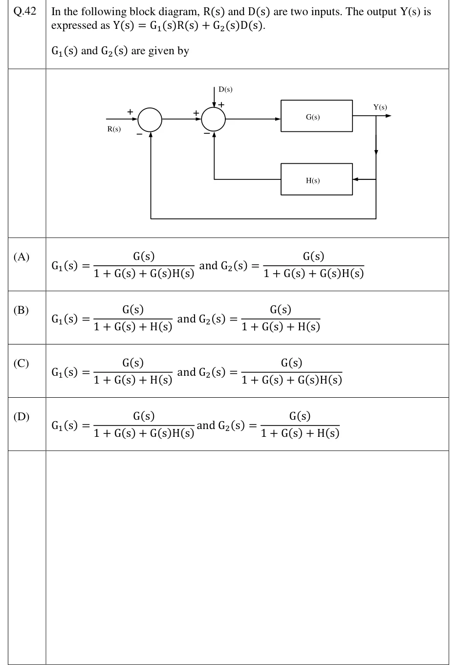
In the following block diagram, and are two inputs. The output is expressed as .
and are given by
 Tap to open full size
Figure description
Two summing junctions in cascade, then a forward block G(s) whose output is Y(s). Summing junction 1: R(s) enters from the left with sign +; a unity feedback path taken straight from Y(s) enters from below with sign -. The output of junction 1 goes to summing junction 2 with sign +. Summing junction 2 also has D(s) entering from the top with sign +, and the output of block H(s) entering from below with sign -. H(s) is fed from Y(s): a branch drops down from the Y(s) take-off point into H(s), which is drawn on the lower path pointing back towards junction 2. The output of junction 2 feeds G(s); the output of G(s) is Y(s). So the loops are: inner loop G(s) with negative feedback H(s) into junction 2, and outer loop G(s) with negative unity feedback from Y(s) into junction 1.
- (A)
and
- (B)
and
- (C)
and
- (D)
and