
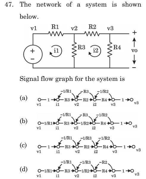
The network of a system is shown below. Signal flow graph for the system is
 Tap to open full size
Figure description
Circuit: source (+ at top) drives node v1. R1 connects v1 to node v2. R3 is a shunt resistor from v2 to the bottom rail. R2 connects v2 to node v3. R4 is a shunt resistor from v3 to the bottom rail. The output vo is across R4 (+ at top, at v3). Mesh currents i1 (left mesh) and i2 (right mesh) are shown by small loop arrows, taken as flowing left to right through R1 and R2. Each option is a signal flow graph with nodes v1, i1, v2, i2, v3 and a unity branch to the output. (a) forward 1, R3, R2, R4, 1; feedback -1/R1, -R3, -1/R2. (b) forward 1/R1, R3, 1/R2, R4, 1; feedback -1/R1, -R3, -1/R2. (c) forward 1, R3, R2, R4, 1; feedback -1/R1, -1/R3, -1/R2. (d) forward 1/R1, R3, 1/R2, R4, 1; feedback -1/R1, -1/R3, -R2.
- (A)
Forward gains 1, R3, R2, R4, 1; feedback gains -1/R1, -R3, -1/R2
- (B)
Forward gains 1/R1, R3, 1/R2, R4, 1; feedback gains -1/R1, -R3, -1/R2
- (C)
Forward gains 1, R3, R2, R4, 1; feedback gains -1/R1, -1/R3, -1/R2
- (D)
Forward gains 1/R1, R3, 1/R2, R4, 1; feedback gains -1/R1, -1/R3, -R2