An antenna converts a guided wave into a radiated one and back, and every standard result in this topic grows from one idea: the far field of a short current element. The Hertzian dipole leads to the half-wave dipole and the quarter-wave monopole over a ground plane, and adding identical elements with chosen phases gives linear arrays. Solving questions here means doing a small set of calculations cleanly: radiation resistance and radiated power, directivity or gain from a radiation-intensity expression, effective aperture and the Friis link budget, and the array factor with its broadside or end-fire phasing, nulls, grating lobes and pattern multiplication.
2 previous-year questions · 2 solved · 5 practice questions
Conventions, field regions and radiated power
Conventions used throughout: SI units, free space unless stated, with ϵ0=8.854×10⁻¹² F/m, μ0=4π×10−7 H/m, c=1/μ0ϵ0≈3×108 m/s and intrinsic impedance η0=μ0/ϵ0≈120π≈377Ω. Fields are phasors with time dependence ejωt, so an outgoing spherical wave carries the factor e−jβr, with β=k=2π/λ=ω/c. Spherical coordinates (r,θ,ϕ) measure θ from the +z axis, with unit vectors a^r,a^θ,a^ϕ. Currents and fields are peak (amplitude) phasors, so every time-average power carries a factor 21. The reflection coefficient at the antenna terminals is Γ=(ZA−Z0)/(ZA+Z0), with ZA the antenna impedance and Z0 the feed-line impedance.
Around any antenna the field falls into regions. Close in, the reactive near field (terms in 1/r2 and 1/r3) stores energy that flows out and back every cycle and carries no net power. Beyond it, in the radiating near-field (Fresnel) region, the angular shape of the field still changes with distance. Far out, in the far-field (Fraunhofer) region, E and H are transverse to a^r, perpendicular to each other and in phase, fall off as 1/r, and satisfy ∣E∣/∣H∣=η. Their angular shape no longer depends on r. That shape is the radiation pattern, and every parameter in this topic (radiation intensity, directivity, beamwidth, gain, array factor) is defined in the far field.
FAR-FIELD DISTANCE
r≥λ2D2,r≫D,r≫λ
D = largest dimension of the antenna (a length here, not the directivity). At r=2D2/λ the path-length difference between the centre and the edge of the antenna is λ/16 (phase error π/8). For an antenna large compared with the wavelength, the reactive near field extends to about r=0.62D3/λ and the radiating near field from there to 2D2/λ. For an electrically small antenna (D≪λ) the binding condition is r≫λ; the radiation and induction terms of a Hertzian dipole are equal in magnitude at r=λ/(2π).
TIME-AVERAGE POWER DENSITY AND TOTAL RADIATED POWER
The middle form holds in the far field only, where E and H are in phase and ∣E∣=η∣H∣.E is a peak phasor. In a lossless medium Prad is the same through every closed surface that encloses the antenna.
EXAM TIP
Peak or rms? These notes use peak values, so P=21I02R and Sav=∣E∣2/(2η). If a question gives rms values, use P=Irms2R and Sav=Erms2/η. The radiation resistance itself is the same either way; only the factor 21 moves.
Hertzian dipole: fields and radiation resistance
The Hertzian (infinitesimal) dipole is a z-directed current element of length dl≪λ at the origin, carrying the same current I0 along its whole length. A common working limit is dl≤λ/50; if the current really is uniform, the results below stay within 1% for dl up to about λ/10. It is the building block of wire antennas: any wire is a superposition of such elements. Its magnetic vector potential is A=a^z4πrμI0dle−jβr, and H=μ1∇×A followed by Maxwell's curl equation for E gives the fields below.
All other components (Eϕ,Hr,Hθ) are zero. Valid for dl≪λ and r≫dl. The 1/r terms are the radiation field, the 1/r2 terms the induction field and the 1/r3 terms (one in Er, one in Eθ) the quasi-static (electric dipole) field. Multiplying out EθHϕ∗ shows that only the product of the two 1/r terms is real, so the induction and quasi-static terms carry no net power.
Close to the dipole (βr≪1) the highest powers of 1/r dominate: E has the shape of an electrostatic dipole's field, H that of the magnetostatic field of a current element, and E and H are 90∘ out of phase, so the power there is mostly reactive. Far away (βr≫1) only the 1/r terms survive, Er becomes negligible, and Eθ and Hϕ form an outgoing spherical wave.
Valid for βr≫1. In free space ∣Eθ∣=λr60πI0dlsinθ V/m. The pattern is ∝sinθ: maximum broadside (θ=90∘), nulls along the axis (θ=0∘,180∘), and the same for every ϕ (omnidirectional in the plane θ=90∘).
HERTZIAN DIPOLE: RADIATED POWER AND RADIATION RESISTANCE
The numerical forms assume free space (η=120π);I0 is the peak current. Rrad grows as (dl/λ)2, which is why electrically short antennas are poor radiators: a small Rrad competes with the ohmic loss resistance.
Radiation resistance is the resistance which, carrying the antenna's reference current, would dissipate exactly the power the antenna radiates: Prad=21I02Rrad. It is part of the real part of the input impedance, and it represents power leaving as radiation, not heat. The ohmic loss resistance Rloss, referred to the same current, accounts for the heat.
SHORT DIPOLE (CURRENT FALLING LINEARLY TO ZERO AT THE ENDS)
Rrad=20π2(λl)2
Centre-fed wire of total length l≪λ (roughly l≤λ/10) with a triangular current: I0 at the feed, zero at the ends. Its average current is I0/2, so its far field is half that of a Hertzian dipole of the same length with current I0: power and Rrad are one quarter. The pattern (sinθ), directivity (1.5) and beamwidth (90∘) are unchanged.
EXAM TIP
Read the current distribution before choosing the formula. 'Hertzian', 'infinitesimal' or 'elementary' dipole, a current element Idl, or a short wire with uniform current (for example a top-loaded one): 80π2(dl/λ)2. A short centre-fed dipole whose current falls to zero at the tips: 20π2(l/λ)2. The directivity is 1.5 in both cases, because the pattern is sinθ in both.
Radiation intensity, directivity, gain and effective aperture
Radiation intensity U(θ,ϕ) is the power radiated per unit solid angle. Because far-field power density falls as 1/r2,U=r2Sav depends on direction only. An isotropic radiator with the same total power would have U=Prad/(4π) in every direction. Directivity compares the actual antenna with that isotropic reference, and gain does the same after charging the antenna for its losses.
A pure ratio set by the shape of the pattern alone; losses do not enter. 'Directivity' with no direction stated means the maximum, D0. dBi means decibels relative to an isotropic radiator; values relative to a half-wave dipole (dBd) are 2.15 dB lower.
BEAM SOLID ANGLE
ΩA=∮Fn(θ,ϕ)dΩ,Fn(θ,ϕ)=UmaxU(θ,ϕ),ΩA≈Θ1Θ2
Fn is the normalized power pattern (=∣E∣2/∣E∣max2).ΩA is the solid angle through which all the power would flow if U stayed at Umax inside it and were zero outside. The approximation uses the half-power beamwidths Θ1 and Θ2 in the two principal planes, in radians, and holds only for a single narrow main lobe with small side lobes.
DIRECTIVITY FROM BEAMWIDTHS (PENCIL BEAMS ONLY)
D0≈Θ1Θ24π(Θ in rad)≈Θ1Θ241253(Θ in degrees)
41253=4π(180/π)2. It ignores the power in side lobes and so tends to overestimate D0. Do not use it for broad patterns such as a dipole's; integrate instead.
Half-power beamwidth (HPBW) is the angle, in a stated plane, between the two directions on either side of the maximum where the radiation intensity falls to half its maximum (field 1/2 of maximum, −3 dB). First-null beamwidth (FNBW) is the angle between the first nulls either side of the main lobe. For the Hertzian dipole, sin2θ=21 at θ=45∘ and 135∘, so its HPBW is 90∘ in any plane containing the dipole axis. Its beam solid angle is ΩA=∮sin2θdΩ=8π/3, giving D0=1.5.
Pin = power accepted at the antenna terminals; Rloss is referred to the same current as Rrad.G≤D, with equality only for a lossless antenna. Gain as defined here excludes impedance mismatch. If the feed line of impedance Z0 is mismatched to the antenna impedance ZA, the realized gain is (1−∣Γ∣2)G with Γ=(ZA−Z0)/(ZA+Z0).
EFFECTIVE APERTURE
Ae=4πλ2G,Pr=SincAe
For a receiving antenna matched to its load and polarization-matched to an incident wave of power density Sinc arriving from the direction in which the gain is G. For a lossless antenna Ae=λ2D/(4π), the maximum effective aperture Aem. Hertzian or short dipole: 3λ2/(8π)≈0.119λ2; half-wave dipole: ≈0.13λ2. For a large aperture antenna (horn, reflector) of physical area Ap,Ae≤Ap, with equality only for uniform, in-phase illumination of a lossless aperture; the ratio Ae/Ap is the aperture efficiency.
EXAM TIP
Directivity by integration, fast. If U=U0cosnθ for 0≤θ≤π/2 and zero below, then Prad=2πU0/(n+1) and D0=2(n+1):n=1 gives 4, n=2 gives 6. If U=U0sin2θ over the full sphere, Prad=8πU0/3 and D0=1.5. First check whether the expression you are given is a field pattern or a power pattern: U goes as the square of the field.
WORKED EXAMPLE
A Hertzian dipole (uniform current) of length 1.5 m radiates in free space at 10 MHz with a peak current of 2 A. Its ohmic loss resistance is 0.5Ω. Find (a) the radiation resistance, (b) the radiated power, (c) the radiation efficiency, (d) the gain in dBi, and (e) the far-field amplitude ∣Eθ∣ at 3 km in the broadside direction.
▸ Solution
λ=c/f=3×108/107=30 m, so dl/λ=1.5/30=0.05. The current is stated to be uniform, so the Hertzian-dipole formulas apply; at this length they are accurate to better than 0.2%.
(a) Rrad=80π2(0.05)2=0.2π2=1.974Ω.
(b) Prad=21I02Rrad=21(2)2(1.974)=3.948 W.
(c) er=1.974+0.51.974=2.4741.974=0.798.
(d) G0=erD0=0.798×1.5=1.197, so G0=10log101.197=0.78 dBi.
(e) 3 km is 100 wavelengths, so this is the far field. ∣Eθ∣=λr60πI0dlsin90∘=30×300060π×2×1.5=6.28×10⁻³ V/m.
Check (e) through power: Umax=D0Prad/(4π)=1.5×3.948/(4π)=0.471 W/sr, so S=Umax/r2=5.24×10−8 W/m², and ∣E∣=2ηS=754×5.24×10−8=6.28×10⁻³ V/m. The two agree.
Answer: (a) 1.97Ω, (b) 3.95 W, (c) 0.798, (d) about 0.78 dBi, (e) about 6.28 mV/m.
Half-wave dipole and quarter-wave monopole
A thin centre-fed dipole of total length l along the z-axis carries a standing-wave current I(z)=Imsin[β(2l−∣z∣)], which is zero at both ends; Im is the standing-wave amplitude. For l=λ/2 this becomes I(z)=I0cosβz for ∣z∣≤λ/4, with its maximum I0=Im at the feed. Summing Hertzian-dipole fields along the wire gives the results below.
Thin wire with the sinusoidal current above, far field. l=λ/2 gives the half-wave result below. For l=λ the pattern is [1+cos(πcosθ)]/sinθ: D0≈2.41 (3.82 dBi), HPBW ≈48∘, and Rrad≈199Ω referred to Im. The broadside directivity peaks near l=1.25λ (D0≈3.28); longer dipoles break into more lobes and the broadside lobe shrinks.
Thin wire, free space for the second form, I0 = peak current at the feed. Nulls along the wire axis, maximum at θ=90∘, omnidirectional in ϕ; the beam is slightly narrower than the Hertzian dipole's sinθ.
In free space Rrad=4πηCin(2π)=30×2.4377≈73.1Ω, where Cin(x)=∫0xt1−costdt, and D0=πRradη=Rrad120≈1.64. Prad=21I02Rrad≈36.5I02 W. The feed sits at a current maximum, so Rrad is also the input resistance. The half-power points are at θ≈51∘ and 129∘. The +j42.5Ω reactance is tuned out by making the dipole slightly shorter than λ/2 (typically about 0.47λ to 0.49λ, shorter for thicker wire); the resistance at resonance is then slightly below 73 Ω.
A monopole is a vertical wire of height h fed against a large conducting ground plane. By image theory, an infinite perfectly conducting plane can be replaced by the mirror image of the current: a vertical current element's image is a vertical element carrying current in the same direction, while a horizontal element's image carries current in the opposite direction. So a monopole plus its image is a dipole of total length 2h, and in the upper half-space (0≤θ≤90∘) the fields are exactly that dipole's. Below the plane there is no field. For the same feed current the monopole therefore radiates only the upper half of the dipole's power, into half the solid angle.
Monopole of height h over an infinite, perfectly conducting ground plane, compared with a dipole of total length 2h with the same current distribution. Same Umax, half the power, hence twice the directivity. A finite or lossy ground changes these values.
h=λ/4 over an infinite perfect ground plane: half the half-wave dipole's impedance, twice its directivity. The pattern above the ground is the half-wave dipole's, with its maximum along the ground plane (θ=90∘) and half power at θ≈51∘, i.e. about 39∘ above the ground plane.
SHORT MONOPOLE
Rrad=160π2(λh)2(uniform current),Rrad=40π2(λh)2(current falling linearly to zero at the top)
Monopole of height h≪λ over an infinite perfect ground plane. From the image rule: the equivalent dipole of length 2h has 80π2(2h/λ)2 or 20π2(2h/λ)2, and the monopole has half of that. The directivity is 3 in both cases (twice 1.5).
Antenna
Current
Rrad
D0
HPBW (E-plane)
Aem
Hertzian dipole, dl≪λ
Uniform, I0
80π2(dl/λ)2
1.5 (1.76 dBi)
90∘
0.119λ2
Short dipole, l≪λ
Triangular, I0 at the feed
20π2(l/λ)2
1.5 (1.76 dBi)
90∘
0.119λ2
Half-wave dipole
I0cosβz,∣z∣≤λ/4
≈73Ω
1.64 (2.15 dBi)
≈78∘
≈0.13λ2
Quarter-wave monopole, infinite perfect ground
I0cosβz,0≤z≤λ/4
≈36.5Ω
3.28 (5.16 dBi)
Maximum along the ground; half power about 39∘ above it
≈0.26λ2
EXAM TIP
Radiation resistance is always quoted for a stated reference current. The general-length formulas refer it to the standing-wave amplitude Im, while the input resistance refers to the feed current I(0)=Imsin(βl/2). For a thin lossless dipole, Rin=Rrad/sin2(βl/2). The two are equal only when l is an odd multiple of λ/2, which is why 73 Ω and 36.5 Ω are also the input resistances of the half-wave dipole and quarter-wave monopole. The relation fails near l=λ,2λ,…, where the feed sits at a current minimum and the input resistance is very large.
EXAM TIP
Monopole trap: with the same feed CURRENT as a dipole, the monopole has the same Umax and half the power. With the same input POWER, the monopole's Umax is double the dipole's, because the power is squeezed into half the space. Either way the directivity doubles.
EXAM TIP
Folded half-wave dipole: a second half-wave conductor of the same radius runs parallel to the first, close to it, and is joined to it at both ends; one conductor is fed at its centre. The two conductors carry equal currents, so for the same radiated power the feed current is halved and the input resistance is about 4×73≈292Ω. The pattern and directivity are those of the ordinary half-wave dipole.
Friis transmission equation
A transmitting antenna of gain Gt is fed with power Pt, and a receiving antenna of gain Gr is a distance R away. In the direction of the receiver the power density is S=PtGt/(4πR2); the product PtGt is the effective isotropic radiated power (EIRP). The receiver collects SAer, where Aer=Grλ2/(4π). Multiplying gives the Friis equation. By reciprocity (linear, passive, isotropic media), an antenna has the same pattern, gain and impedance whether it transmits or receives.
FRIIS TRANSMISSION EQUATION
PtPr=GtGr(4πRλ)2=λ2R2AetAer
Conditions: each antenna in the other's far field, free space with no obstacles or multipath, both antennas matched to their lines and to each other in polarization, and Gt,Gr taken in the direction of the other antenna. Use gains, not directivities, when the antennas have loss. (4πR/λ)2 is the free-space path loss.
P(dBm)=10log10(P/1mW). The constant 32.44 dB uses c=3×10⁸ m/s (the exact speed of light gives 32.45 dB). With fixed gains, LFS rises by 6 dB for every doubling of distance or of frequency. With fixed effective apertures instead, the received power rises with frequency, because λ2 then sits in the denominator.
FRIIS EQUATION WITH MISMATCH AND POLARIZATION LOSS
Pr=PtGtGr(4πRλ)2(1−∣Γt∣2)(1−∣Γr∣2)PLF
Γt,Γr = reflection coefficients at the two antenna terminals. PLF = polarization loss factor: cos2ψp for two linearly polarized antennas whose polarization directions are at angle ψp (so 0 for orthogonal linear polarizations), and 0.5 between a linearly polarized and a circularly polarized antenna.
EXAM TIP
Friis traps. (1) Convert dBi to a ratio before multiplying (G=10GdBi/10), or stay in dB and add; never mix the two. (2) λ is the free-space wavelength at the operating frequency. (3) Power falls as 1/R2 but field strength as 1/R: doubling the distance halves the field and quarters the power (−6 dB).
WORKED EXAMPLE
A 3 GHz point-to-point link in free space uses a transmitter power of 5 W, a transmitting antenna of gain 20 dBi and a receiving antenna of gain 15 dBi, 2 km apart. Both antennas are matched, aligned boresight to boresight and polarization-matched. Take c=3×10⁸ m/s. Find the received power in dBm and in watts, and the effective aperture of the receiving antenna.
Pr=36.99+20+15−108.00=−36.0 dBm, i.e. 10−3.60 mW =2.50×10⁻⁷ W =0.25μW.
Receiving aperture: Gr=101.5=31.62, so Aer=4πGrλ2=4π31.62×0.01=0.0252 m².
Check by power density: S=4πR2PtGt=4π(2000)25×100=9.95×10⁻⁶ W/m², and SAer=9.95×10−6×0.0252=2.50×10⁻⁷ W. The two agree.
Answer:Pr≈−36.0 dBm ≈0.25μW; Aer≈0.025 m².
Linear arrays and pattern multiplication
An array feeds several identical elements with chosen amplitudes and phases to shape a beam no single element could. In the far field every element sees the observer in the same direction θ, and the elements' distances differ only in the phase term. Element n at z=nd is nearer the observer by ndcosθ, so its field arrives with extra phase βndcosθ; the difference in the 1/r amplitude is negligible. The sum of these phasors, with each element's own feed phase added, is the array factor.
N identical, identically oriented elements on the z-axis at spacing d, equal amplitudes, element n fed with I0ejnα (α = progressive phase, positive when each element leads the one before it). θ is measured from the array axis; for an array along another axis use the cosine of the angle from that axis (for the x-axis, sinθcosϕ).∣AF∣ has its maximum value N at ψ=0, and again at ψ=±2π,±4π,… if those values are reached.
TWO-ELEMENT ARRAY
∣AF∣=1+ejψ=2cos2ψ,ψ=βdcosθ+α
Two equal-amplitude elements, the one at z=d leading the one at z=0 by α. Nulls where ψ=±π, provided that value lies in the visible range α−βd≤ψ≤α+βd (for example, d=λ/4 with α=0 has no null at all). With unequal amplitudes, I2/I1=k,∣AF∣=∣1+kejψ∣, whose minimum (reached where ψ=±π is visible) is ∣1−k∣: there is no complete null unless k=1.
Set ψ=0 in the wanted direction; a real beam direction exists only if ∣α∣≤βd. With the ejωt convention the beam leans toward the end whose elements lag: for end-fire along +z, each element lags the one before it by βd, exactly the phase a wave travelling along +z picks up between elements. Varying α electronically steers the beam (a phased array).
NULLS AND SIDE LOBES OF A UNIFORM ARRAY
ψnull=±N2mπ,m=1,2,3,…(m=N,2N,…);first side lobe≈−13.3dB near ψ≈±N3π(large N)
Solve βdcosθ+α=ψnull for θ and keep only solutions with ∣cosθ∣≤1. Small arrays have higher side lobes (about −11.3 dB for N=4). With uniform amplitudes, changing d or α only moves the side lobes in angle (or out of the visible range); lowering their level needs a tapered amplitude distribution.
Uniform array with α=0;m=1,2,… with mλ/(Nd)≤1 and m not a multiple of N. The approximate forms (in radians unless marked) need Nd≫λ. The beamwidth depends on the array length Nd, not on N alone.
Uniform array with α=−βd, beam toward θ=0∘;m=1,2,… with mλ/(Nd)≤2 and m not a multiple of N. The square-root approximations (radians) need Nd≫λ. For the same length, the end-fire beam is much wider than the broadside beam in the plane containing the axis, but it is a pencil beam around the axis instead of a fan all round it.
Uniform amplitudes, beam toward θ=0∘, large N. The extra phase π/N puts ψ=0 just outside the visible range, which narrows the main beam. The spacing makes ψ=−π at θ=180∘, which keeps the back radiation small. The price is higher side lobes. The factor 1.8 is approximate (about 1.79 to 1.81 for N from 10 to 50).
CONDITION FOR NO GRATING LOBES
d<λ(broadside),d<2λ(ordinary end-fire),d<1+∣cosθ0∣λ(beam steered to θ0)
A grating lobe is a second full maximum (∣AF∣=N), where ψ=±2π. As θ runs from 0∘ to 180∘,ψ covers the visible range α−βd≤ψ≤α+βd; there is no grating lobe if this range contains no multiple of 2π other than the main beam's ψ=0. At exactly d=λ (broadside) grating lobes appear along the axis; at exactly d=λ/2 (end-fire) a second beam appears at θ=180∘.
DIRECTIVITY OF UNIFORM ARRAYS OF ISOTROPIC ELEMENTS (APPROXIMATE)
D0≈2Nλd(broadside),D0≈4Nλd(ordinary end-fire)
Valid for Nd≫λ and no grating lobes. For a broadside array with d=λ/2,D0=N exactly, for any N (see the exact formula below).
EXACT DIRECTIVITY OF A UNIFORM ARRAY OF ISOTROPIC ELEMENTS
D0=N+2∑n=1N−1(N−n)cos(nα)nβdsin(nβd)N2
Equal amplitudes, progressive phase α, valid when the main beam ψ=0 lies in the visible range (∣α∣≤βd). When βd is a multiple of π (for example d=λ/2), every sine vanishes and D0=N for any α; this includes the two-beam end-fire array at d=λ/2. The same happens for end-fire at d=λ/4 with α=−π/2, because cos(nπ/2)sin(nπ/2)=0.
PATTERN MULTIPLICATION
Etotal(θ,ϕ)=Eelement(θ,ϕ)×AF(θ,ϕ)
For identical, identically oriented elements; the array factor carries the feed amplitudes and phases, and mutual coupling is ignored. In dB the two patterns add. A null of either factor is a null of the total, and the total maximum lies where the product peaks, which need not be at the maximum of either factor.
Pattern multiplication also works for arrays of arrays: a set of identical sub-arrays spaced along an axis is itself an array whose 'element' is the sub-array. The binomial array is the standard case. Its amplitudes are binomial coefficients (1:2:1, 1:3:3:1, ...), because (1+ejψ)N−1 expands into exactly those coefficients, so an N-element binomial array is N−1 two-element arrays multiplied together. At d=λ/2 broadside, ∣AF∣n=cos(2πcosθ)N−1: no side lobes at all, but a wider main beam than a uniform array of the same length.
Analysing an array pattern
Place the array on an axis, pick element 0 as the reference, and write ψ=βdcosγ+α, where γ is the angle from the array axis and α is the progressive phase (positive = each element leads the one before it).
Find the visible range: as γ goes from 0∘ to 180∘,ψ runs from α+βd down to α−βd.
Main beam(s): ψ=0, plus ψ=±2π,±4π,… if they fall in the visible range (grating lobes).
Nulls: ψ=±2mπ/N with m not a multiple of N (for two elements, ψ=±π) inside the visible range; convert each to γ.
Multiply by the element pattern and add the element's own nulls (pattern multiplication).
Directivity and beamwidth from the formulas above, or by integrating ∣Etotal∣2 when the elements are not isotropic.
EXAM TIP
Watch the angle and the sign. The array factor depends on the angle from the ARRAY AXIS: for an array along x it is a function of sinθcosϕ, which in the xy-plane is cosϕ. And these formulas take α as the phase by which each element LEADS the one before it: if the element at larger z lags by 90∘, then α=−90∘ and the beam leans toward +z.
EXAM TIP
An end-fire array at d=λ/2 is a trap: with α=−π the visible range is −2π≤ψ≤0, so there is a second full beam at θ=180∘ and the array radiates equally both ways along its axis. Single-direction end-fire needs d<λ/2, and a two-element cardioid needs d=λ/4 with α=−π/2.
WORKED EXAMPLE
A uniform linear array of 10 isotropic elements lies along the z-axis. (a) With d=λ/2, find the progressive phase for a broadside beam, the first-null directions, the FNBW, the approximate HPBW and the directivity. (b) The same array is re-phased for ordinary end-fire toward +z. Is d=λ/2 acceptable? (c) With d=λ/4, find α, the FNBW, the approximate HPBW and the directivity of the end-fire array.
▸ Solution
(a) Broadside: α=0.βd=π and Nd=5λ.
First nulls: cosθ=±λ/(Nd)=±0.2, so θ=78.46∘ and 101.54∘. FNBW =101.54∘−78.46∘=23.1∘ (the approximation 2λ/(Nd)=0.4 rad =22.9∘ is close).
Directivity: broadside with d=λ/2 gives D0=N=10 exactly, i.e. 10 dB.
(b) End-fire toward +z needs α=−βd=−π. The visible range is then −2π≤ψ≤0, and ψ=−2π occurs at θ=180∘: a grating lobe as strong as the main beam. So d=λ/2 is not acceptable for a single end-fire beam.
(c) βd=π/2, so α=−π/2 and Nd=2.5λ. The visible range −π≤ψ≤0 contains no −2π, so there is no grating lobe.
First null: cosθ=1−λ/(Nd)=1−0.4=0.6, so θ=53.13∘ and FNBW =2×53.13∘=106.3∘.
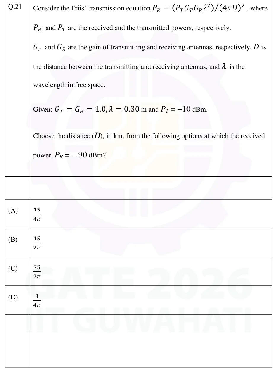
Consider the Friis' transmission equation PR=(PTGTGRλ2)/(4πD)2, where PR and PT are the received and the transmitted powers, respectively. GT and GR are the gain of transmitting and receiving antennas, respectively, D is the distance between the transmitting and receiving antennas, and λ is the wavelength in free space.
Given: GT=GR=1.0,λ=0.30m and PT=+10dBm.
Choose the distance (D), in km, from the following options at which the received power, PR=−90dBm?
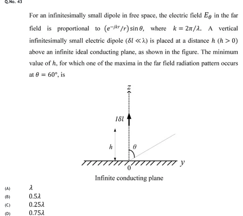
For an infinitesimally small dipole in free space, the electric field Eθ in the far field is proportional to (e−jkr/r)sinθ, where k=2π/λ. A vertical infinitesimally small electric dipole (δl≪λ) is placed at a distance h (h>0) above an infinite ideal conducting plane, as shown in the figure. The minimum value of h, for which one of the maxima in the far field radiation pattern occurs at θ=60∘, is
Tap to open full sizeFigure from the GATE 2020 EC paper. It is part of the question.Figure description
A horizontal hatched line is the infinite conducting plane, labelled 'Infinite conducting plane' beneath it; the origin 0 is marked on it and the horizontal axis to the right is labelled y. A dotted vertical line rises from the origin and is labelled Z at the top, with an arrowhead. On this z-axis, at height h above the plane, sits a short upward arrow labelled I delta l (the vertical current element, pointing in +z). A double-headed vertical arrow to the left, running from the plane up to the dipole, is labelled h. A thin straight line leaves the origin up and to the right into the first quadrant (the observation direction), and the angle between it and the vertical z-axis is marked theta with a small arc.
A Hertzian dipole of length 2 cm carries a uniform current and radiates in free space at 300 MHz. Take c=3×10⁸ m/s. Its radiation resistance, in ohms (rounded off to three decimal places), is ______.
▸ Answer and solution
Answer:0.316 (accepted range ±0.003)
λ=3×10⁸/(3×108)=1 m, so dl/λ=0.02.
Rrad=80π2(dl/λ)2=80×9.8696×4×10−4=0.316Ω.
PRACTICE 22 marks · MCQ
Two identical Hertzian dipoles, both oriented along the x-axis, are placed on the z-axis at z=+λ/4 and z=−λ/4 and fed with equal, in-phase currents. In which directions is the total far field zero?
(A)
Along ±z only
(B)
Along ±x and ±z
(C)
Along ±y and ±z
(D)
Along ±x only
▸ Answer and solution
Answer: (B)
Element pattern: an x-directed dipole radiates as the sine of the angle from its own axis, 1−sin2θcos2ϕ. It is zero along ±x and equal to 1 along ±y and ±z.
Array factor (origin at the centre, d=λ/2,α=0, array along z):∣AF∣=2∣cos(2πcosθ)∣. It is zero at θ=0∘,180∘ (±z) and equal to 2 everywhere in the xy-plane.
By pattern multiplication the total is zero along ±x (element null) and along ±z (array null). Along ±y both factors are at their maximum, so the total is maximum there.
PRACTICE 31 mark · MCQ
A quarter-wave monopole stands on an infinite, perfectly conducting ground plane. Compared with a half-wave dipole in free space carrying the same feed current, the monopole has
(A)
the same radiation resistance and the same directivity
(B)
half the radiation resistance and twice the directivity
(C)
twice the radiation resistance and half the directivity
(D)
half the radiation resistance and the same directivity
▸ Answer and solution
Answer: (B)
By image theory the monopole and its image form a half-wave dipole, so above the ground plane the fields, and hence Umax, equal the dipole's.
There is no field below the plane, so for the same current the monopole radiates half the power: Rrad=73/2=36.5Ω.
Same Umax with half the power gives D0=4πUmax/Prad doubled: 2×1.64=3.28.
PRACTICE 42 marks · NAT
A 10 GHz link operates in free space. The transmitter delivers 100 W to a matched antenna of gain 20 dBi, and a receiving antenna of gain 30 dBi is 5 km away. The two antennas face each other along their boresights, and the receiving antenna is matched to its load and polarization-matched. Take c=3×10⁸ m/s. The power delivered to the receiver load, in microwatts (rounded off to two decimal places), is ______.
▸ Answer and solution
Answer:2.28 (accepted range ±0.03)
λ=3×10⁸/1010=0.03 m. Gt=100,Gr=1000.
Receiving aperture: Aer=Grλ2/(4π)=1000×9×10−4/(4π)=0.0716 m².
Power density at the receiver: S=PtGt/(4πR2)=104/(4π×2.5×107)=3.183×10−5 W/m².
Pr=SAer=3.183×10−5×0.0716=2.28×10⁻⁶ W =2.28μW.
Check in dB: LFS=20log10(4π×5000/0.03)=126.42 dB, so Pr=50+20+30−126.42=−26.42 dBm =2.28μW.
PRACTICE 52 marks · MSQ
A uniform linear array of N=4 isotropic elements lies along the z-axis with spacing d=λ/2 and progressive phase α (each element leads the previous one by α), with θ measured from the +z axis. Which of the following statements is/are correct?
(A)
With α=0, the first nulls on either side of the main beam are at θ=60∘ and θ=120∘.
(B)
With α=−π, the array has a single main beam, directed along θ=0∘.
(C)
The normalized array factor can be written as 4sin(ψ/2)sin2ψ with ψ=πcosθ+α.
(D)
With α=0, the directivity is exactly 4.
▸ Answer and solution
Answer: (A), (C), (D)
βd=π, so ψ=πcosθ+α and ∣AF∣n=∣sin(Nψ/2)/(Nsin(ψ/2))∣=∣sin2ψ/(4sin(ψ/2))∣. C is correct.
A: with α=0 the first nulls are at ψ=±2π/4, i.e. πcosθ=±π/2,cosθ=±0.5,θ=60∘,120∘. Correct.
B: with α=−π,ψ=π(cosθ−1) runs from 0 at θ=0∘ to −2π at θ=180∘. At ψ=−2π,∣AF∣=N again, so there is a second full beam at θ=180∘. Incorrect.
D: a broadside array of isotropic elements with d=λ/2 has D0=N exactly, here 4. Correct.