
IAE Academy

GATE 2025 EE Q.60: solution and answer

GATE 2025 · EEQ.60 · 2 marks · NAT

The steady state capacitor current of a conventional DC-DC buck converter, working in CCM, is shown in one switching cycle. If the input voltage is 30 V, the value of the inductor used, in mH, is ____________ (round off to one decimal place).
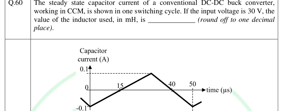
GATE 2025 EE question 60: Plot of capacitor current (A) versus time (µs).Tap to open full size
Figure from the GATE 2025 EE paper. It is part of the question.
Figure description

Plot of capacitor current (A) versus time (µs). Vertical axis marked 0.1 (dashed line from the peak), 0 and -0.1; horizontal axis marked 15, 40 and 50 µs (a dashed vertical line drops from the 50 µs mark to the minimum). The waveform is a triangle: it falls to its minimum of -0.1 A at t = 0, rises linearly, crosses zero at 15 µs, reaches its peak of +0.1 A at about 30 µs, then falls linearly, crossing zero at 40 µs and reaching -0.1 A again at 50 µs, where the next cycle begins.

Answer and solution

ANSWER

The inductance is .

Official answer: 1.7 to 1.9Source: Official answer key, GATE 2025 EE (IIT Roorkee)

  1. In steady state the average capacitor current is zero, and in a buck converter the capacitor carries the ripple part of the inductor current. So the plotted triangle is the inductor ripple, and its peak-to-peak value is .

  2. From the figure, the minimum occurs at and again at , so the switching period is .

  3. The inductor current rises while the switch is ON. The rising line goes from at to at , so its slope is . Reaching the peak, , means a rise of , which takes . Check on the falling side: from the peak at the current crosses zero at ( in ) and reaches at , as plotted.

  4. So , , and the duty ratio is .

  5. For the buck converter in CCM, .

  6. During the ON interval the inductor voltage is , so .

  7. Check with the OFF interval, where the inductor voltage is : , the same value.

KEY IDEA

In a buck converter the capacitor current is the inductor current minus its average, so the plotted triangle is the inductor ripple. The ON time read from the rising edge gives . Then .

WATCH OUT FOR

Taking the rise time as the zero crossing at or the fall crossing at instead of the peak at , which gives the wrong duty ratio. Another slip is using (the peak) instead of the peak-to-peak .

From the GATE 2025 EE paper. Every question of this paper · Download the full paper · All 9 DC-DC converters questions, with notes

More DC-DC converters questions