
IAE Academy

GATE 2020 EE Q.50: solution and answer

GATE 2020 · EEQ.50 · 2 marks · NAT

In the dc-dc converter circuit shown, switch Q is switched at a frequency of 10 kHz with a duty ratio of 0.6. All components of the circuit are ideal, and the initial current in the inductor is zero. Energy stored in the inductor in mJ (rounded off to 2 decimal places) at the end of 10 complete switching cycles is ______.
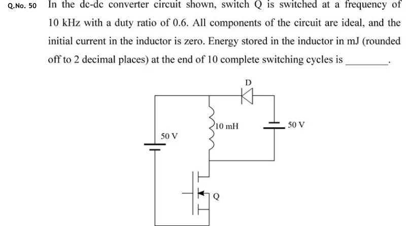
GATE 2020 EE question 50: A 50 V source on the left with its positive terminal at the top.Tap to open full size
Figure from the GATE 2020 EE paper. It is part of the question.
Figure description

A 50 V source on the left with its positive terminal at the top. The top wire runs from the source's positive terminal to the right, to a diode D whose arrow points left (anode on the right; cathode on the left, towards the source and the inductor's top). The diode's right end connects to the top of a 50 V battery. The battery's short plate (negative) is on top and its long plate (positive) is below. A 10 mH inductor hangs from the top wire. Its lower end joins the node that connects the battery's bottom (positive) terminal and the top (drain) of switch Q, a MOSFET at the bottom. Q's source returns through the bottom wire to the negative terminal of the 50 V source.

Answer and solution

ANSWER

The energy stored in the inductor after 10 complete switching cycles is 5.00 mJ. The inductor current is 1 A at that point.

Official answer: 4.95 to 5.05Source: Official answer key, GATE 2020 EE (IIT Delhi)

  1. Data: , , , , so . The duty ratio is , so and . Call the inductor's top end node A (the source's positive rail) and its bottom end node B (the drain of Q). Take the inductor current as positive from A to B.

  2. Q ON: node B is connected to the source's negative terminal, so . The battery's positive terminal is at B (0 V), so its negative terminal, which is the diode's anode, sits at . The cathode is at , so D is reverse biased and blocks. The current rises:

  3. Q OFF: cannot change instantly. It flows from B into the battery's positive terminal, out of its negative terminal, through D (anode to cathode) and back to A. Around this loop, , so : the battery absorbs energy and the current falls:

  4. Check that the current never reaches zero. In cycle 1 it rises from to and falls to , so it stays positive and D conducts for the whole off interval. Each later cycle starts higher, so the same holds every cycle and the conduction is continuous.

  5. Net change per cycle: . Equivalently, the volt-seconds do not balance: per cycle, and .

  6. At the end of 10 complete cycles (each cycle ends at the end of its off interval): .

  7. Energy stored:

KEY IDEA

The inductor sees +50 V for and −50 V (the battery) for . With the volt-seconds do not balance, so the current climbs by A in every cycle. After 10 cycles it is 1 A, and .

WATCH OUT FOR

Reading the right-hand battery the wrong way up. If you do, the inductor seems to see +50 V all the time and you get 125 mJ. Read the polarity from the plate lengths: the long plate is positive. Another slip is to assume steady state (zero net change per cycle). This circuit starts from zero current and is not in steady state, because the volt-seconds per cycle are not zero when .

From the GATE 2020 EE paper. Every question of this paper · Download the full paper · All 9 DC-DC converters questions, with notes

More DC-DC converters questions