
IAE Academy

GATE 2018 EE Q.53: solution and answer

GATE 2018 · EEQ.53 · 2 marks · NAT

A dc to dc converter shown in the figure is charging a battery bank, B2 whose voltage is constant at 150 V. B1 is another battery bank whose voltage is constant at 50 V. The value of the inductor, L is 5 mH and the ideal switch, S is operated with a switching frequency of 5 kHz with a duty ratio of 0.4. Once the circuit has attained steady state and assuming the diode D to be ideal, the power transferred from B1 to B2 (in Watt) is ____________ (up to 2 decimal places).
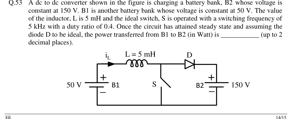
GATE 2018 EE question 53: Battery B1 of 50 V (positive terminal up) at the left, in series with inductor L = 5 mH carrying current i_L to the right…Tap to open full size
Figure from the GATE 2018 EE paper. It is part of the question.
Figure description

Battery B1 of 50 V (positive terminal up) at the left, in series with inductor L = 5 mH carrying current i_L to the right (arrow pointing right). After the inductor the top rail has a node: from this node a switch S goes down to the bottom rail (shunt switch), and the top rail continues through diode D (anode toward the inductor, cathode toward the right) to the positive terminal (top) of battery B2 of 150 V at the right. The bottom rail connects the negative terminals of B1 and B2 and the bottom of S. This is a boost converter topology with the output held by a battery.

Answer and solution

ANSWER

The power transferred from B1 to B2 is 12.00 W.

Official answer: 12.0Source: Official answer key, GATE 2018 EE (IIT Guwahati)

  1. The circuit is a boost converter: source (B1) feeds , the switch S shunts the node after , and the diode D leads to the 150 V battery B2. Duty ratio , , so .

  2. Which mode? In continuous conduction, volt-second balance would need . The battery holds the output at 150 V, which is higher. The inductor therefore demagnetises faster than in CCM, and its current reaches zero before the period ends. The diode blocks reverse current, so the converter runs in discontinuous conduction (DCM). Steps 3 to 5 confirm this.

  3. S on for : , so the current rises linearly from zero to

  4. S off, D conducting: , so the current falls to zero in

  5. Since , the current stays zero for the last of the period. This confirms DCM and is consistent with the assumption in step 2.

  6. The source current is the inductor current. Its average is the area of the triangle (base , height ) divided by :

  7. Power taken from B1: .

  8. Cross-check at B2: the diode carries current only during , so and . This equals the power drawn from B1, as it must for ideal components.

KEY IDEA

When the output is a fixed battery higher than , the boost converter cannot stay in CCM. Find the peak current from , find the fall time from , and average the triangular current over the full period.

WATCH OUT FOR

Using the CCM relation, which gives a power of -style or with treated as a flat current. Another slip is averaging the triangle over instead of the full period , which gives A and W instead of W.

From the GATE 2018 EE paper. Every question of this paper · Download the full paper · All 9 DC-DC converters questions, with notes

More DC-DC converters questions