
IAE Academy

GATE 2018 EE Q.50: solution and answer

GATE 2018 · EEQ.50 · 2 marks · NAT

The figure shows two buck converters connected in parallel. The common input dc voltage for the converters has a value of 100 V. The converters have inductors of identical value. The load resistance is 1 Ω. The capacitor voltage has negligible ripple. Both converters operate in the continuous conduction mode. The switching frequency is 1 kHz, and the switch control signals are as shown. The circuit operates in the steady state. Assuming that the converters share the load equally, the average value of i_S1, the current of switch S1 (in Ampere), is _____ (up to 2 decimal places).
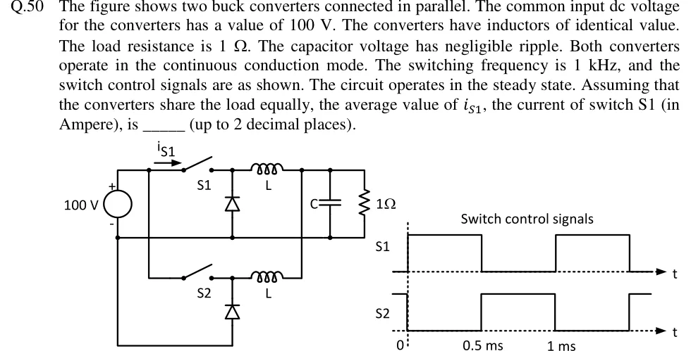
GATE 2018 EE question 50: A 100 V dc source (+ at top) feeds two buck stages sharing the same input rails.Tap to open full size
Figure from the GATE 2018 EE paper. It is part of the question.
Figure description

A 100 V dc source (+ at top) feeds two buck stages sharing the same input rails. Upper stage: switch S1 in series with the top rail (current i_S1 flowing from the source through S1 to the right), then inductor L to the output node; a freewheeling diode from the junction of S1 and L down to the negative rail, with its cathode at the S1-L junction (anode on the bottom rail side). Lower stage: switch S2 and inductor L in the same arrangement with its own diode returning to the negative rail. Both inductors join at the output node, which has capacitor C and the 1 ohm load resistor in parallel to the negative rail. Switch control signals plotted against time t: S1 is high from 0 to 0.5 ms and low from 0.5 ms to 1 ms, then repeats; S2 is low from 0 to 0.5 ms and high from 0.5 ms to 1 ms, then repeats (complementary to S1).

Answer and solution

ANSWER

The average value of is .

Official answer: 11.50 to 13.50Source: Official answer key, GATE 2018 EE (IIT Guwahati)

  1. Switch S1 is on from to in a period of , so the duty ratio is . S2 is on in the other half of the period, so it has the same .

  2. Both converters run in continuous conduction from the same input with the same . With negligible capacitor ripple, .

  3. Load current: .

  4. The converters share the load equally, so each average inductor current is .

  5. In a buck converter the switch carries the inductor current only while it is on, a fraction of each period. The diode carries the inductor current for the rest of the period. The ripple does not change the average, because the average of the switch current over a period is times the average inductor current.

  6. Average switch current: .

  7. Check by power balance: each converter delivers , so the current drawn from the source is . This current flows only through S1, so it is the average of .

KEY IDEA

Each buck converter has , so and the load takes . Each converter supplies through its inductor, and the switch conducts that current for the fraction of the period, giving .

WATCH OUT FOR

Giving , the average inductor current, as the average switch current. The switch conducts only during the on-time, so its average is . Another slip is taking the full load current as the share of one converter.

From the GATE 2018 EE paper. Every question of this paper · Download the full paper · All 9 DC-DC converters questions, with notes

More DC-DC converters questions