
IAE Academy

GATE 2026 EE Q.48: solution and answer

GATE 2026 · EEQ.48 · 2 marks · MCQ

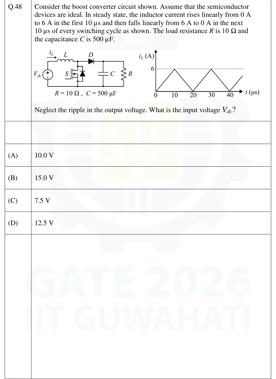
Consider the boost converter circuit shown. Assume that the semiconductor devices are ideal. In steady state, the inductor current rises linearly from 0 A to 6 A in the first 10 µs and then falls linearly from 6 A to 0 A in the next 10 µs of every switching cycle as shown. The load resistance R is 10 Ω and the capacitance C is 500 µF. Neglect the ripple in the output voltage. What is the input voltage V_dc?
GATE 2026 EE question 48: Left: boost converter.Tap to open full size
Figure from the GATE 2026 EE paper. It is part of the question.
Figure description

Left: boost converter. Source V_dc (+ at top) in series with inductor L (current i_L flowing left to right) to the switch-diode node. MOSFET S (with its body diode) connects from that node to the bottom rail. Diode D goes from that node to the output node (anode at the node), then capacitor C and load R in parallel from the output node to the bottom rail. Labelled R = 10 Ω, C = 500 µF. Right: plot of i_L (A) versus t (µs): a triangular waveform from 0 at t = 0 rising to 6 A at 10 µs (dashed line marks 6), falling to 0 at 20 µs, rising to 6 A at 30 µs, falling to 0 at 40 µs, and so on. The time axis is marked 0, 10, 20, 30, 40.

  1. (A)

    10.0 V

  2. (B)

    15.0 V

  3. (C)

    7.5 V

  4. (D)

    12.5 V

Answer and solution

ANSWER

, option (C).

Official answer: CSource: Official answer key, GATE 2026 EE (IIT Guwahati)

  1. Read the waveform: the current rises for and falls for , so and the duty ratio is . The current just reaches at the end of each cycle, so the converter is at the boundary of continuous and discontinuous conduction. The peak current is .

  2. The diode conducts only while S is off, as a ramp falling from to . Its average current over the full cycle is

  3. With negligible output ripple, the average capacitor current over a cycle is zero. So the average diode current equals the load current: .

  4. Output voltage: .

  5. Find the input voltage from the inductor. While S is on, the inductor voltage is , so . While S is off, the inductor voltage is , and the current falls from to , so . Equating the two gives , so This agrees with the ideal boost relation at .

  6. Check by power balance: the average inductor (input) current is (the triangle's mean), so . The output power is . They agree, so , option (C).

KEY IDEA

Read , and the peak current from the triangular waveform. The average diode current equals the load current, which gives . Then volt-second balance on the inductor with the current returning to zero gives .

WATCH OUT FOR

Taking the load current as the average inductor current () instead of the average diode current () gives and a wrong . Another slip is to stop at and pick option (B), which is the output voltage, not the input voltage.

From the GATE 2026 EE paper. Every question of this paper · Download the full paper · All 9 DC-DC converters questions, with notes

More DC-DC converters questions