
IAE Academy

GATE 2023 EE Q.23: solution and answer

GATE 2023 · EEQ.23 · 1 mark · MCQ

The chopper circuit shown in figure (i) feeds power to a 5 A DC constant current source. The switching frequency of the chopper is 100 kHz. All the components can be assumed to be ideal. The gate signals of switches S1 and S2 are shown in figure (ii). Average voltage across the 5 A current source is
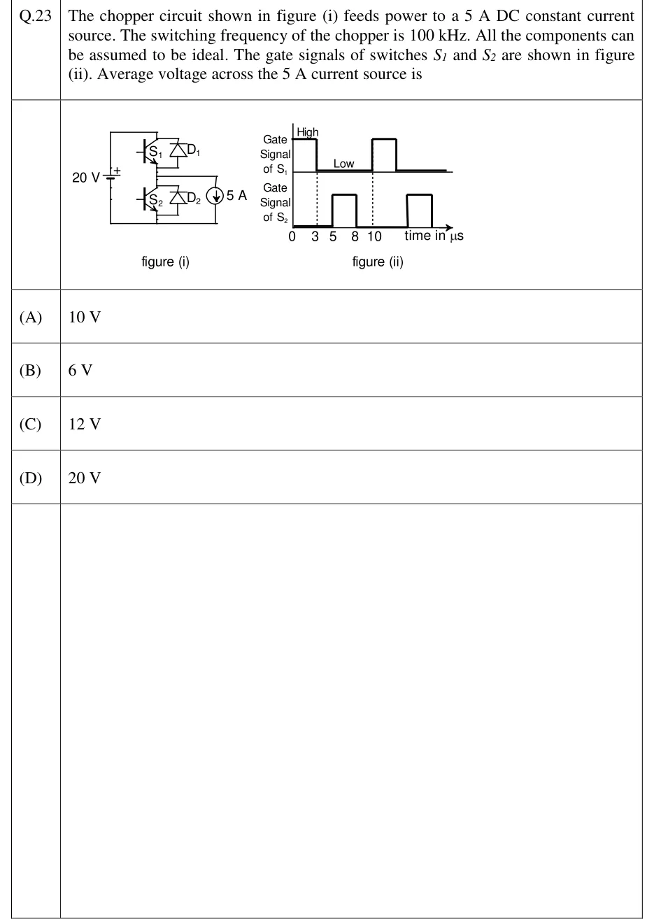
GATE 2023 EE question 23: Figure (i): a 20 V DC source (+ terminal at top) feeds a half-bridge leg.Tap to open full size
Figure from the GATE 2023 EE paper. It is part of the question.
Figure description

Figure (i): a 20 V DC source (+ terminal at top) feeds a half-bridge leg. Top IGBT S1 with anti-parallel diode D1 connects the positive rail to the midpoint; bottom IGBT S2 with anti-parallel diode D2 connects the midpoint to the negative rail. A 5 A DC constant current source is connected from the midpoint to the negative rail, with its arrow pointing down (current leaves the midpoint). Figure (ii): time axis in microseconds marked 0, 3, 5, 8, 10. Gate signal of S1 is High from 0 to 3 us, Low from 3 to 10 us, then High again from 10 us (period 10 us). Gate signal of S2 is Low from 0 to 5 us, High from 5 to 8 us, Low from 8 to 10 us, then High again from 15 to 18 us.

  1. (A)

    10 V

  2. (B)

    6 V

  3. (C)

    12 V

  4. (D)

    20 V

Answer and solution

ANSWER

The average voltage across the 5 A current source is 6 V (option B).

Official answer: BSource: Official answer key, GATE 2023 EE (IIT Kanpur)

  1. The switching frequency is , so the period is . From figure (ii), S1 is ON from to and OFF from to , so the duty ratio of S1 is . (No firing angle is involved: this is a DC chopper.)

  2. The current source is connected from the midpoint of the leg to the negative rail, and its arrow points downward. The load current therefore always leaves the midpoint and flows down into the negative rail. The voltage across the current source is the midpoint voltage measured with respect to the negative rail.

  3. Interval to : S1 is ON, so the source drives the through S1 into the midpoint. Hence .

  4. Interval to : S1 is OFF. The current source still takes out of the midpoint, so that current must reach the midpoint from the negative rail, flowing upward. Only the anti-parallel diode D2 can carry current in that direction, so D2 conducts and clamps the midpoint to the negative rail: .

  5. S2 is ON from to , but this changes nothing. An IGBT carries current only from collector to emitter, that is from the midpoint down to the negative rail, whereas the current needed here is upward. So D2 still carries the current and throughout to (all components are ideal).

  6. The average voltage over one period is which equals .

  7. The average voltage across the current source is , option (B).

KEY IDEA

With a constant current load flowing in one direction, the midpoint voltage is the supply while S1 conducts and zero while the freewheeling diode D2 carries the current, whatever S2's gate signal does. The average is therefore .

WATCH OUT FOR

Treating S2's ON interval (5 to 8 microseconds) as a conducting path that changes the midpoint voltage, or assuming the output is held at 20 V for the whole of S1's gate-high time plus S2's pulse. S2 cannot carry the upward current, so D2 conducts and the output stays at 0 V.

From the GATE 2023 EE paper. Every question of this paper · Download the full paper · All 9 DC-DC converters questions, with notes

More DC-DC converters questions