GATE 2026 EE Q.17
A 15 kVA, 1100 V/220 V, single-phase two-winding transformer is configured as a 1.32 kV/1.1 kV autotransformer. What will be the rating of the autotransformer?
- (A)
60 kVA
- (B)
75 kVA
- (C)
90 kVA
- (D)
100 kVA

GATE EE · IN
Single-phase, three-phase and auto-transformers
Single-phase transformer: the EMF equation, ideal and practical models, referred equivalent circuits and the phasor diagram, open- and short-circuit tests, voltage regulation (including the zero- and maximum-regulation conditions), efficiency, maximum efficiency and all-day efficiency. Three-phase transformers: connections and their line-voltage ratios, vector groups, and parallel operation with circulating current and load sharing. Auto-transformers: power conducted versus transformed, copper saving, and the rating obtained by reconnecting a two-winding transformer. Six practice questions with worked solutions close the topic.
14 previous-year questions · 13 solved · 6 practice questions
A transformer transfers electrical power between two or more windings linked by a common magnetic core, by mutual induction. The frequency is unchanged; the voltage and current levels generally change.
Conventions used throughout these notes. Voltages and currents are rms phasors; is the imaginary unit. Winding 1 is the primary (connected to the supply) and winding 2 the secondary (connected to the load). The turns ratio is . Subscript means "total, referred to the primary" and means "total, referred to the secondary". The load power factor is , with for a lagging (inductive) load. Three-phase quantities are per phase unless stated. Efficiency is output/input.
EMF EQUATION (RMS INDUCED VOLTAGE OF A WINDING)
in V, in Hz, = turns of that winding, = peak core flux in Wb (, with the net iron cross-section). The derivation assumes the core flux is sinusoidal. It applies to the primary and secondary separately, each with its own .
IDEAL TRANSFORMER RELATIONS
An ideal transformer has no winding resistance, no leakage flux, no core loss and an infinitely permeable core, so it needs no magnetising current. In a practical transformer, holds only approximately (closest at no load), and holds only when the no-load current is neglected.
CORE FLUX IS SET BY THE APPLIED VOLTAGE AND FREQUENCY
Since , the peak flux depends on the applied voltage and frequency and is nearly independent of load. Raising at fixed , or lowering at fixed , increases and drives the core towards saturation.
Where a practical transformer departs from the ideal
Winding resistances , cause (copper) loss, which varies as the square of the load current.
Leakage flux that links only one winding is represented by leakage reactances , . The series drops across the resistances and leakage reactances together make the terminal voltage change with load (voltage regulation).
The core has finite permeability, so a magnetising current is drawn even at no load. It is represented by a magnetising reactance in the shunt (exciting) branch.
Hysteresis and eddy currents in the core cause core (iron) loss, represented by a resistance in the shunt branch. At constant applied voltage and frequency this loss is essentially constant and independent of load current.
COMPONENTS OF CORE LOSS
= hysteresis loss (the Steinmetz exponent is empirical, commonly taken as 1.6). = eddy-current loss, where is the lamination thickness. With : at constant , and . At constant , . At constant , does not depend on , and .
For calculation, every quantity on one side is referred to the other side through the turns ratio. The transformer then becomes a single circuit with one series impedance and one shunt (exciting) branch. Referral does not change power, losses or per-unit values.
REFERRING SECONDARY QUANTITIES TO THE PRIMARY
Here . To refer a primary quantity to the secondary, use the inverse: , , . An impedance always grows when it is referred to the side with more turns.
TOTAL SERIES IMPEDANCE REFERRED TO EACH SIDE
and . In the approximate equivalent circuit the shunt branch ( in parallel with ) is moved to the supply terminals, ahead of the series impedance. This is justified because the no-load current is a small fraction of rated current.
PHASOR RELATIONS OF THE APPROXIMATE CIRCUIT (REFERRED TO THE SECONDARY)
The dot convention has entering the dotted primary terminal and leaving the dotted secondary terminal. With as the reference phasor, a lagging load has .
Constructing the phasor diagram (lagging load). Draw as the reference. Draw lagging it by . From the tip of , add parallel to , then leading by . The resulting phasor is , and it is longer than for a lagging load. On the primary side, the mutual flux lags by (almost exactly) , and the induced emfs , lag by . The no-load current lags by the no-load angle , which is close to . Its component is in phase with and supplies the core loss. Its component is in phase with and magnetises the core.
EXAM TIP
Fix the sign convention before any regulation or phasor problem. Take as the reference and for a lagging load. For a leading load, changes sign in every formula that follows, so the reactive-drop term is subtracted instead of added.
Open-circuit (OC) test
Rated voltage at rated frequency is applied to one winding, usually the LV winding (a convenient supply voltage), with the other winding open.
The meters read the applied voltage , the no-load current (a few percent of rated current) and the input power .
Because the core flux is at its rated value and is small, the copper loss is negligible. is therefore, to a close approximation, the core loss at rated voltage.
The test gives the shunt-branch parameters and , referred to the winding on which it was performed.
SHUNT BRANCH FROM THE OC TEST (REFERRED TO THE TESTED SIDE)
These values hold at the voltage and frequency of the test. Core loss is not linear in flux, so and are not constants at other voltages.
Short-circuit (SC) test
One winding is short-circuited, usually the LV winding. The other (usually the HV winding) is supplied through a variable voltage, which is raised from zero until rated current flows. The HV side is chosen because its rated current is smaller, and a few percent of the HV rating is an easy voltage to supply and measure.
The meters read the applied voltage , the current and the input power .
The series impedance is small, so is only a small percentage of rated voltage. The core flux, and with it the core loss, is therefore negligible, and is essentially the copper loss at current .
The test gives the total series impedance (, or , , according to which side is energised). It does not give the shunt branch. Applying rated voltage to a shorted transformer would drive a current many times the rated value.
SERIES IMPEDANCE FROM THE SC TEST (REFERRED TO THE ENERGISED SIDE)
and are referred to the energised winding. Multiply or divide by before combining them with quantities on the other side.
COPPER LOSS AT ANOTHER CURRENT, AND PERCENTAGE IMPEDANCE
If the SC test was not run at rated current, scale its reading by the square of the current ratio to get the full-load copper loss. is the SC-test voltage at rated current, expressed as a percentage of rated voltage. It has the same value whichever side it is calculated on, provided , and all belong to that side.
Sumpner's (back-to-back) test
Two identical transformers are used. Their primaries are connected in parallel across rated voltage and frequency, and their secondaries in series opposition, so the two secondary emfs cancel around the secondary loop.
The wattmeter in the primary supply reads the core loss of both transformers ().
A small voltage injected into the secondary loop circulates rated current. The wattmeter in that circuit reads the full-load copper loss of both ().
Both transformers carry rated flux and rated current at the same time while the supply provides only the losses. The test is therefore suitable for a full-load temperature-rise (heat run) test.
WORKED EXAMPLE
An OC test on the LV side of a single-phase transformer gives , , . An SC test, supplied from the LV side with the HV side shorted, gives , , , where is the rated LV current. Find , , and , all referred to the LV side.
OC test: , so .
and .
and .
SC test: .
.
.
Answer: , , and , all referred to the LV side because both tests were supplied from the LV side. The full-load copper loss is (the SC test ran at rated current) and the core loss at rated voltage is .
Voltage regulation is the change in secondary terminal voltage between no load and full load, with the primary voltage held constant. It is caused entirely by the series impedance. In the approximate circuit the shunt branch plays no part.
DEFINITION
is the no-load secondary voltage and the full-load (rated) secondary voltage. Some texts divide by instead ("regulation down"). These notes use the rated full-load voltage as the base.
APPROXIMATE (FIRST-ORDER) REGULATION
Use for a lagging and for a leading power factor. and are the rated current and voltage on the same side as , (that is, , with primary quantities, or , with secondary quantities). and are the percentage resistance and reactance. The formula neglects the quadrature component of the drop.
SECOND-ORDER REGULATION (LAGGING PF)
and are in percent. For a leading power factor, replace with . The second term is the quadrature drop's contribution. Use this form only when a question asks for more accuracy than the first-order formula gives.
CONDITION FOR ZERO REGULATION (FIRST-ORDER FORMULA)
Zero regulation is possible only at a leading power factor, where the resistive drop in phase with is cancelled by the component of the reactive drop. At any leading power factor more leading than this, the regulation is negative: the terminal voltage rises on load.
CONDITION FOR MAXIMUM REGULATION
Obtained by setting . Maximum regulation occurs when the load power-factor angle equals the impedance angle of the series impedance, and its value is then the percentage impedance.
WORKED EXAMPLE
A transformer has and (referred to the secondary), rated secondary voltage and rated secondary current . Using the first-order formula, find the lagging power factor at which the regulation is maximum, and the value of that maximum.
Condition: , so lagging.
, so .
.
Answer: The maximum regulation is about , at lagging ().
EFFICIENCY AT LOAD FRACTION X
is the rated VA. is the output. is the constant core loss (from the OC test at rated voltage). is the full-load copper loss (from the SC test at rated current). The formula assumes the terminal voltage stays at its rated value.
MAXIMUM EFFICIENCY (AT A GIVEN POWER FACTOR)
Efficiency is highest at the load where the variable copper loss equals the constant core loss. That load is VA, or . The load fraction does not depend on power factor. The value of does: it is highest at unity power factor.
ALL-DAY (ENERGY) EFFICIENCY
This is the ratio of energy output to energy input over 24 hours, with in hours and . The core loss is counted for all 24 h, including no-load periods, because it is present whenever the transformer is energised. Copper loss is counted only for the hours the transformer carries each load.
Ordinary (power) efficiency vs all-day (energy) efficiency
Aspect | Ordinary efficiency | All-day efficiency |
|---|---|---|
Basis | Power output / power input at one load | Energy output / energy input over 24 h |
Core loss | at that instant | (Wh), whatever the loading pattern |
Copper loss | at that load | , only over loaded hours |
Where it matters | Power transformers, which run near full load while in service | Distribution transformers, which stay energised all day with a varying load and are therefore designed for low core loss |
In a three-phase transformer, the per-phase turns ratio is (turns of one HV phase winding over turns of one LV phase winding). For a star winding, and . For a delta winding, and . The total rating is on either side.
Common three-phase connections (HV–LV)
Connection | Line-voltage ratio | Phase shift and notes |
|---|---|---|
Star–star (Yy) | Even clock number (0 or 6 with standard marking). Without a neutral connection or a delta tertiary, the phase voltages can carry third-harmonic distortion, and unbalanced load shifts the neutral. | |
Delta–delta (Dd) | Even clock number. If one of three single-phase units is removed, the remaining two can still supply a three-phase load as an open delta (V–V connection) at reduced rating. | |
Star–delta (Yd) | Odd clock number (an odd multiple of ; 1 or 11 with standard marking). The delta provides a path for third-harmonic magnetising current. Commonly used for step-down at the receiving end. | |
Delta–star (Dy) | Odd clock number. An LV neutral is available (e.g. Dyn11) for earthing and single-phase loads. Commonly used for step-up at generating stations and for distribution. |
OPEN-DELTA (V–V) RATING
is the rating of the full bank of three identical units. In open delta each remaining unit carries line current, so the bank delivers of the full-bank rating, which is of the combined rating of the two units in service.
Vector group notation (clock method)
A vector group such as Dyn11 reads as follows. The capital letter is the HV winding connection (Y, D, or Z for zigzag). The lower-case letter is the LV winding connection (y, d or z). The letter n (N on the HV side) means the neutral is brought out. The number is the clock number.
Clock number : the LV phasor lags the corresponding HV phasor (line-to-neutral) by . Picture the HV phasor at 12 o'clock and the LV phasor at o'clock. So , , lag, and lag, which means the LV phasor leads by .
Yy and Dd connections give even clock numbers (multiples of ). Yd and Dy connections give odd clock numbers (odd multiples of ).
Transformers to be paralleled must have the same phase displacement and the same phase sequence. A unit can never be paralleled with a unit or with a unit, whatever external connections are used.
Conditions for satisfactory parallel operation
Same rated line-voltage ratio. Otherwise a circulating current flows even at no load.
Correct polarity, the same phase sequence and the same phase displacement (compatible vector groups). A mismatch here gives a large voltage difference around the loop and a very large circulating current.
Equal per-unit impedance, each on its own kVA rating, so that the load divides in proportion to the ratings and neither unit is overloaded first.
Equal ratios, so that the two currents are in phase and the transformers can together deliver the sum of their ratings.
CIRCULATING CURRENT (UNEQUAL VOLTAGE RATIOS)
and are the open-circuit secondary emfs. and are the ohmic series impedances referred to the secondary. The current flows at no load and adds to each unit's load current.
LOAD SHARING BETWEEN TWO PARALLELED TRANSFORMERS (EQUAL VOLTAGE RATIOS)
and are complex ohmic impedances referred to the same side. and are per-unit impedances, each on its own transformer's rating. Each unit's share is inversely proportional to its ohmic impedance. The share is proportional to its rating only when . The unit with the lower per-unit impedance takes more than its proportional share and reaches full load first.
WORKED EXAMPLE
Transformer A (, ) and transformer B (, ) have the same voltage ratio and the same ratio. They share a load. Find each load, and the largest total load the pair can carry without overloading either unit.
.
and .
B is overloaded by while A is at .
B reaches its rating first: .
Answer: and (B is overloaded). The maximum load without overloading either unit is , less than the sum of the ratings.
An auto-transformer has a single winding, part of which (the common winding) is shared by the input and output circuits. Part of the power is transferred by conduction and only the rest by induction. For the same output this saves copper and core material and reduces losses. The cost is that there is no electrical isolation between the two circuits. In what follows, is the auto-transformer's own voltage ratio, whichever way it is used (step-up or step-down), and losses and magnetising current are neglected.
POWER CONDUCTED AND POWER TRANSFORMED
The common winding carries and the series winding carries . Only passes through transformer action, so the windings and core need only be sized for .
COPPER SAVING COMPARED WITH A TWO-WINDING TRANSFORMER
This compares the same output and the same voltages, with the same current density and the same mean length of turn in both designs. The saving approaches 100% as and is small for large ratios. For example, saves 50% and saves only 25%.
TWO-WINDING TRANSFORMER RECONNECTED AS AN AUTO-TRANSFORMER
Each winding keeps its rated voltage and current, so the inductively transformed power equals the two-winding rating . The auto-transformer's losses are the same as the two-winding transformer's, but its output is larger, so its efficiency is higher. Its per-unit series impedance on its own rating is times that of the two-winding transformer. This gives lower regulation and a higher short-circuit current.
WORKED EXAMPLE
A , two-winding transformer has a full-load efficiency of at unity power factor. It is reconnected as an auto-transformer with its windings in series-aiding. Find the rating for (a) a connection and (b) a connection, and the full-load unity-pf efficiency in case (a).
Rated currents: HV winding ; LV winding .
(a) : the winding is the series winding and carries the line current of . . Check: , .
(b) : the winding is the series winding and carries . . Check: , .
Full-load losses of the two-winding transformer: . The losses are unchanged after reconnection.
(a) .
Answer: (a) with ; (b) . The closer the ratio is to 1, the larger the gain in rating.
EXAM TIP
Two fractions, easily swapped. The inductively transformed fraction equals the copper ratio . The conducted fraction equals the copper saving. For , 75% of the power is transformed, the auto-transformer uses 75% of the copper, and the saving is 25%.
PREVIOUS-YEAR QUESTIONS
Try each question first, then open the answer. One shows the official answer only. We placed each question under a topic ourselves; the exam paper does not label topics.
See these papers in full: GATE EE 2026 · GATE EE 2025 · GATE EE 2024 · GATE EE 2023 · GATE EE 2020 · GATE EE 2018 · GATE IN 2026 · GATE IN 2024 · GATE IN 2023
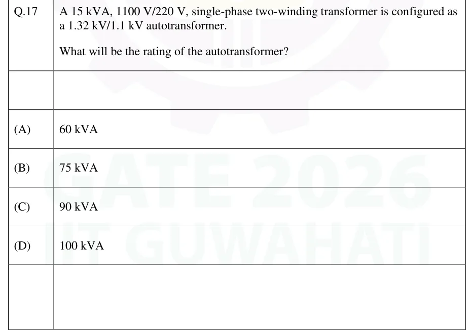
A 15 kVA, 1100 V/220 V, single-phase two-winding transformer is configured as a 1.32 kV/1.1 kV autotransformer. What will be the rating of the autotransformer?
60 kVA
75 kVA
90 kVA
100 kVA
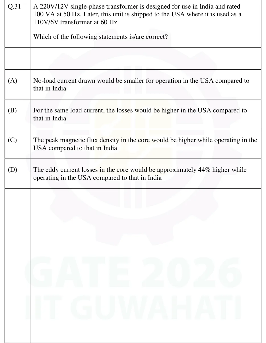
A 220V/12V single-phase transformer is designed for use in India and rated 100 VA at 50 Hz. Later, this unit is shipped to the USA where it is used as a 110V/6V transformer at 60 Hz.
Which of the following statements is/are correct?
No-load current drawn would be smaller for operation in the USA compared to that in India
For the same load current, the losses would be higher in the USA compared to that in India
The peak magnetic flux density in the core would be higher while operating in the USA compared to that in India
The eddy current losses in the core would be approximately 44% higher while operating in the USA compared to that in India
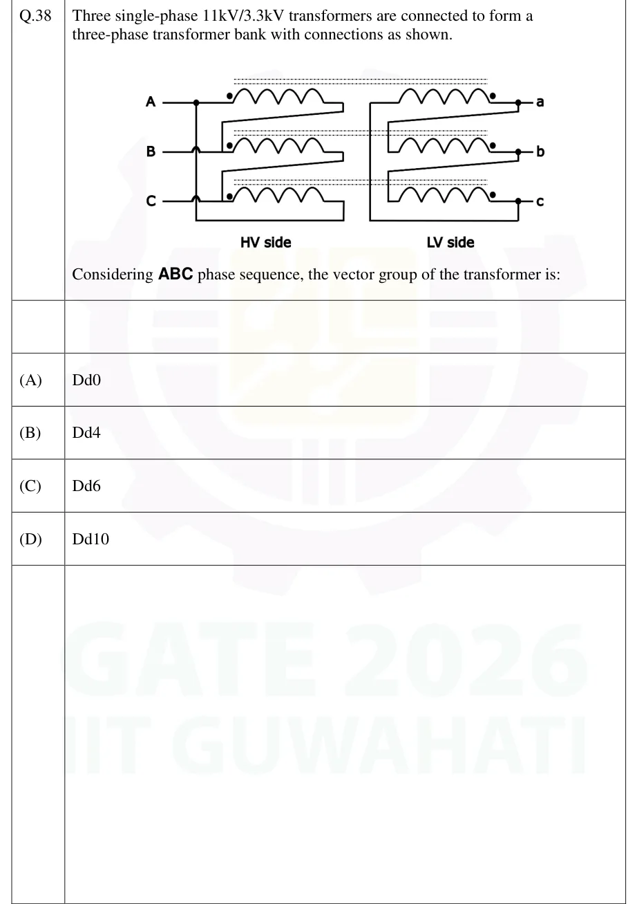
Three single-phase 11kV/3.3kV transformers are connected to form a three-phase transformer bank with connections as shown. [Figure: HV side has three single-phase transformer primary windings, one per phase, fed from lines A, B, C, each winding's dotted terminal connected directly to its own line (A, B, C respectively); a diagonal jumper connects the undotted (finish) end of the A-winding to the dotted (start) junction of the B-winding, and another diagonal jumper connects the finish of the B-winding to the start junction of the C-winding; the finish of the C-winding returns, via a bus that runs down the left side of the HV block crossing (without connecting, shown as wire hops) the B and C line taps, to the A line junction — this closes the HV windings into a delta A→B→C→A. Each HV winding is drawn on the same magnetic-core row (linked by a dashed line denoting the shared core) as one LV winding: row 1 = HV-A with LV winding for terminal a, row 2 = HV-B with LV-b, row 3 = HV-C with LV-c. On the LV side the windings are mirrored left–right: each winding's dotted terminal is on the right, tied directly to its own line (a, b, c); a diagonal jumper connects the dotted/line junction of a to the undotted (finish) end of winding b; another diagonal jumper connects the dotted/line junction of b to the finish end of winding c; the finish end of winding a is returned, via a bus running down the far-left side of the LV block (crossing, without connecting, past the b and c rows) and along the bottom, up to the dotted/line junction of c — closing the LV windings into a delta whose loop order is a→c→b→a. Both sides are labelled 'HV side' and 'LV side' respectively.] Considering ABC phase sequence, the vector group of the transformer is:
 Tap to open full size
Three single-phase transformer units drawn as three horizontal rows. In each row the primary (HV) winding is on the left half and the secondary (LV) winding is on the right half, magnetically linked (same core) as shown by a dashed line spanning that row. Row 1: HV winding fed from line A (dot at the A-line end) coupled to an LV winding terminating at line a (dot at the a-line end). Row 2: HV winding fed from line B (dot at B) coupled to LV winding terminating at line b (dot at b). Row 3: HV winding fed from line C (dot at C) coupled to LV winding terminating at line c (dot at c). HV interconnection (forming a delta): the non-dot (finish) end of the row-1 (A) winding is joined by a diagonal wire down to the dot/start junction of the row-2 (B) winding; the finish of the B winding is joined by a diagonal wire down to the dot/start junction of the row-3 (C) winding; the finish of the C winding is carried by a wire along the bottom and up a left-hand vertical bus (which crosses the B and C line taps without electrical connection, shown by small hop/loop symbols) back up to the A line junction — closing the loop A(dot)-wdgA-finish=B(dot)-wdgB-finish=C(dot)-wdgC-finish=A(dot). LV interconnection (also a delta, mirrored left-right): the dot ends of the LV windings are on the right, each tied directly to its line (a, b, c); a diagonal wire joins the a-line junction down to the non-dot (finish) end of winding b; a second diagonal wire joins the b-line junction down to the finish end of winding c; the finish end of winding a is carried down a far-left vertical bus (crossing the b and c rows without connecting) and along the bottom up to the c-line junction — closing the loop a(dot)-wdga-finish=c(dot)-wdgc-finish=b(dot)-wdgb-finish=a(dot), i.e. the LV delta's internal loop runs in the order a→c→b→a, the reverse of the HV loop's A→B→C→A.
Dd0
Dd4
Dd6
Dd10
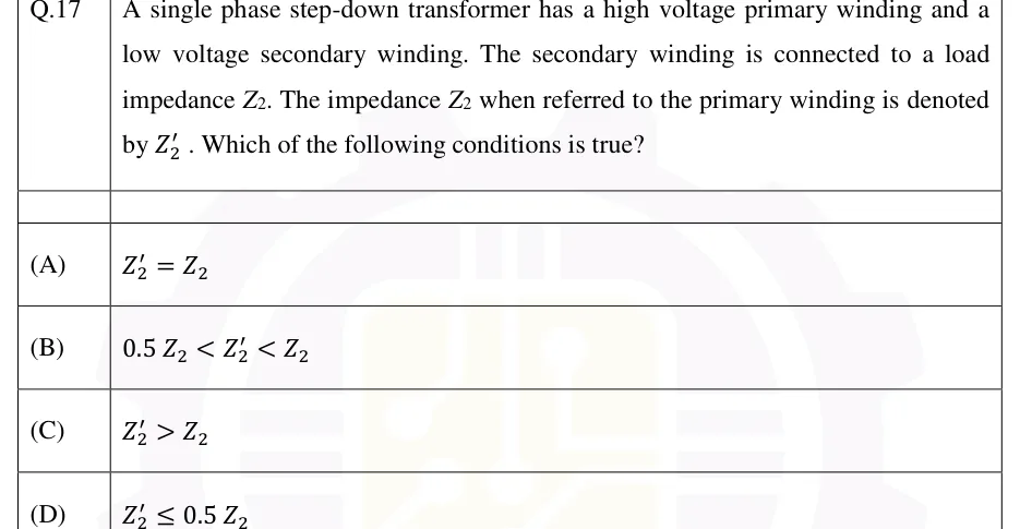
A single phase step-down transformer has a high voltage primary winding and a low voltage secondary winding. The secondary winding is connected to a load impedance . The impedance when referred to the primary winding is denoted by . Which of the following conditions is true?
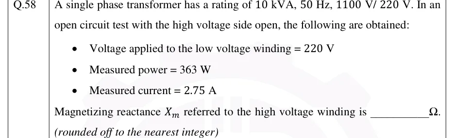
A single phase transformer has a rating of 10 kVA, 50 Hz, 1100 V/ 220 V. In an open circuit test with the high voltage side open, the following are obtained:
- Voltage applied to the low voltage winding = 220 V
- Measured power = 363 W
- Measured current = 2.75 A
Magnetizing reactance referred to the high voltage winding is __________ Ω.
(rounded off to the nearest integer)
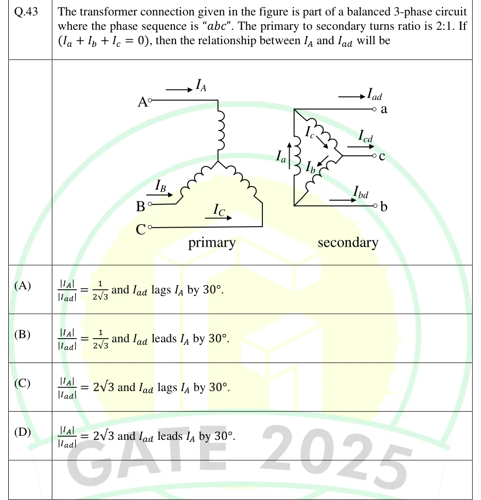
The transformer connection given in the figure is part of a balanced 3-phase circuit where the phase sequence is "abc". The primary to secondary turns ratio is 2:1. If (I_a + I_b + I_c = 0), then the relationship between I_A and I_ad will be
 Tap to open full size
Primary side (left): three line terminals A, B, C each feeding a winding (shown as coil loops) that connect down into a star-type interconnection; line currents are marked I_A (into terminal A, arrow pointing right/into the winding), I_B (into terminal B), and I_C (into terminal C), each with an arrow showing the reference direction into the transformer. Secondary side (right): a delta (triangular) winding arrangement with three output terminals a, b, c tapped from the delta corners; internal winding (phase) currents are labelled I_a (vertical arrow, left side of the triangle), I_b (diagonal arrow, lower part of the triangle) and I_c (diagonal arrow, upper part of the triangle), circulating around the closed delta loop. The external line currents drawn off the delta corners are labelled I_ad (top, leaving terminal a), I_cd (middle, leaving terminal c) and I_bd (bottom, leaving terminal b). Labels 'primary' and 'secondary' appear below each side of the figure.
|I_A|/|I_ad| = 1/(2√3) and I_ad lags I_A by 30°.
|I_A|/|I_ad| = 1/(2√3) and I_ad leads I_A by 30°.
|I_A|/|I_ad| = 2√3 and I_ad lags I_A by 30°.
|I_A|/|I_ad| = 2√3 and I_ad leads I_A by 30°.
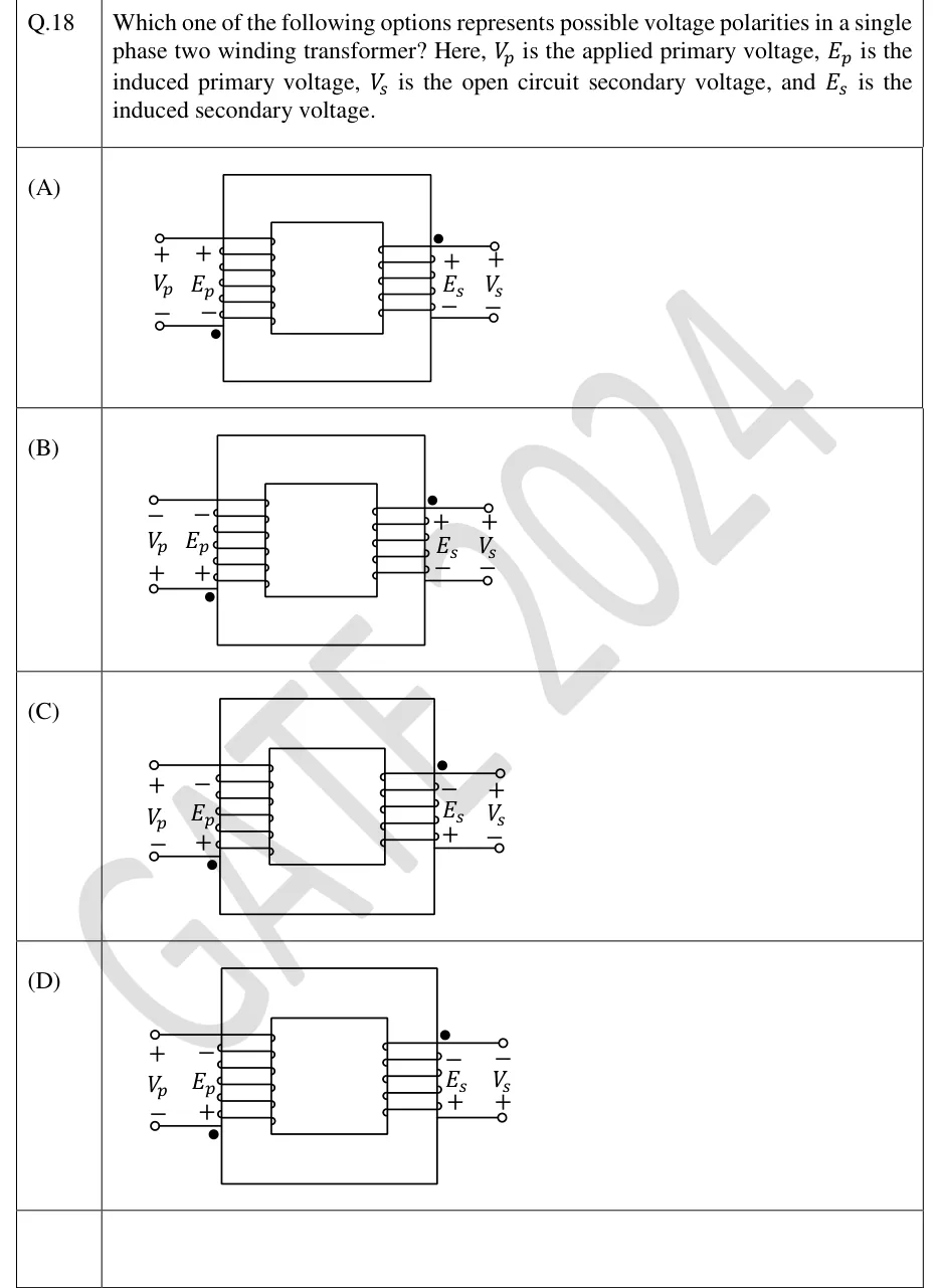
Which one of the following options represents possible voltage polarities in a single phase two winding transformer? Here, is the applied primary voltage, is the induced primary voltage, is the open circuit secondary voltage, and is the induced secondary voltage.
 Tap to open full size
Each option (A)-(D) shows the same core transformer schematic: two windings on a common rectangular core, primary winding on the left with two external terminals (top and bottom, each shown as a small circle 'o'), secondary winding on the right likewise with top and bottom terminals. In every option the dot (filled circle '•') mark on the primary is at its BOTTOM terminal (next to the label E_p) and the dot on the secondary is at its TOP terminal (next to the label E_s) — dot placement is identical in all four options; only the +/- polarity labels differ. Labels read outward from the winding: primary column order (left to right) is V_p terminal, then E_p terminal (winding lead); secondary column order is E_s terminal (winding lead) then V_s terminal. Polarity signs per option, top/bottom: (A) top: V_p+,E_p+; bottom(dot): V_p-,E_p- | top(dot): E_s+,V_s+; bottom: E_s-,V_s-. (B) top: V_p-,E_p-; bottom(dot): V_p+,E_p+ | top(dot): E_s+,V_s+; bottom: E_s-,V_s-. (C) top: V_p+,E_p-; bottom(dot): V_p-,E_p+ | top(dot): E_s-,V_s+; bottom: E_s+,V_s-. (D) top: V_p+,E_p-; bottom(dot): V_p-,E_p+ | top(dot): E_s-,V_s-; bottom: E_s+,V_s+.
Figure — polarities as listed above for (A)
Figure — polarities as listed above for (B)
Figure — polarities as listed above for (C)
Figure — polarities as listed above for (D)
A 50 kVA transformer has an efficiency of 95% at full load and unity power factor. Assume the core losses are negligible. The efficiency of the transformer at 75% of the full load and 0.8 power factor is ________% (rounded off to one decimal place).
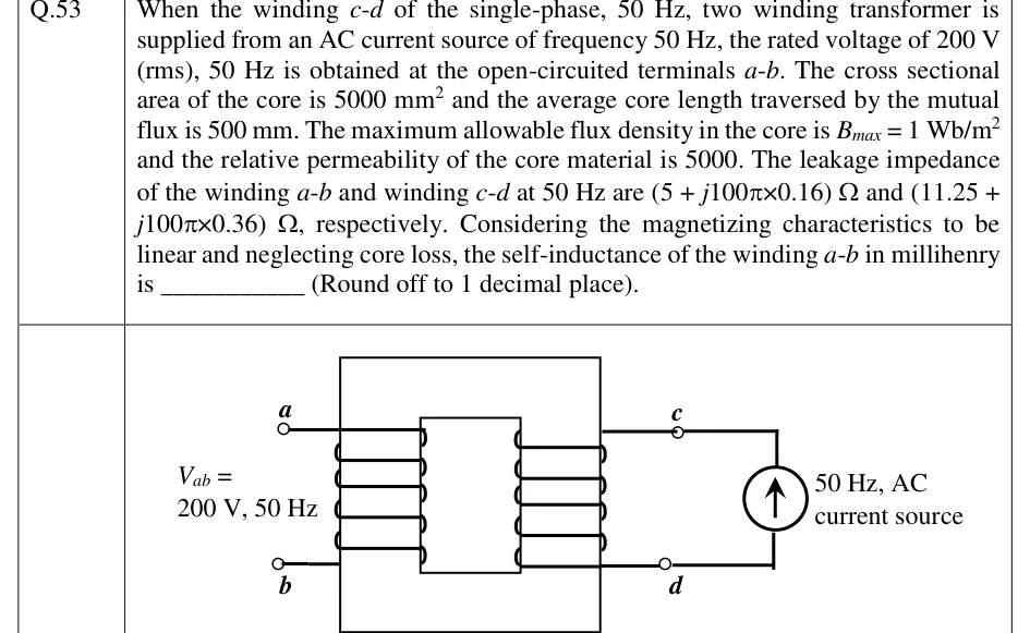
(NAT, 2 marks) When the winding c-d of the single-phase, 50 Hz, two winding transformer is supplied from an AC current source of frequency 50 Hz, the rated voltage of 200 V (rms), 50 Hz is obtained at the open-circuited terminals a-b. The cross sectional area of the core is 5000 mm^2 and the average core length traversed by the mutual flux is 500 mm. The maximum allowable flux density in the core is B_max = 1 Wb/m^2 and the relative permeability of the core material is 5000. The leakage impedance of the winding a-b and winding c-d at 50 Hz are (5 + j100π×0.16) Ω and (11.25 + j100π×0.36) Ω, respectively. Considering the magnetizing characteristics to be linear and neglecting core loss, the self-inductance of the winding a-b in millihenry is ______ (Round off to 1 decimal place).
 Tap to open full size
A single-phase two-winding transformer schematic. A rectangular core window is drawn with two vertical windings side by side sharing the same magnetic core (a large outer rectangle representing the core, with an inner vertical divider). The left winding is labelled with terminals a (top) and b (bottom), open-circuited, with the annotation 'V_ab = 200 V, 50 Hz' written beside it (this is the induced open-circuit voltage, not an applied source). The right winding is labelled with terminals c (top) and d (bottom); c and d are connected externally to an AC current source, drawn as a circle with an upward arrow inside it, labelled '50 Hz, AC current source'. Both windings are drawn as coils wound on the same core limb region (mutually coupled), with small circles at each winding's terminals denoting the winding ends a, b, c, d.
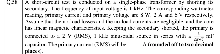
A short-circuit test is conducted on a single-phase transformer by shorting its secondary. The frequency of input voltage is 1 kHz. The corresponding wattmeter reading, primary current and primary voltage are 8 W, 2 A and 6 V respectively. Assume that the no-load losses and the no-load currents are negligible, and the core has linear magnetic characteristics. Keeping the secondary shorted, the primary is connected to a 2 V (RMS), 1 kHz sinusoidal source in series with a mF capacitor. The primary current (RMS) will be _____ A (rounded off to two decimal places).
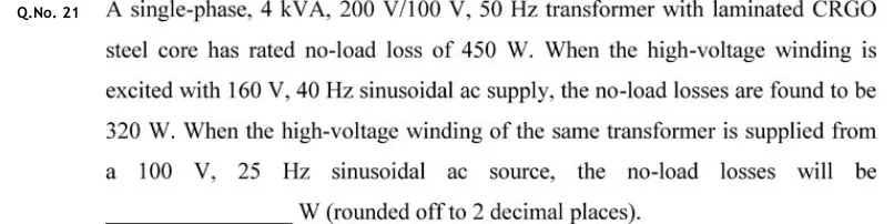
A single-phase, 4 kVA, 200 V/100 V, 50 Hz transformer with laminated CRGO steel core has rated no-load loss of 450 W. When the high-voltage winding is excited with 160 V, 40 Hz sinusoidal ac supply, the no-load losses are found to be 320 W. When the high-voltage winding of the same transformer is supplied from a 100 V, 25 Hz sinusoidal ac source, the no-load losses will be _______ W (rounded off to 2 decimal places).
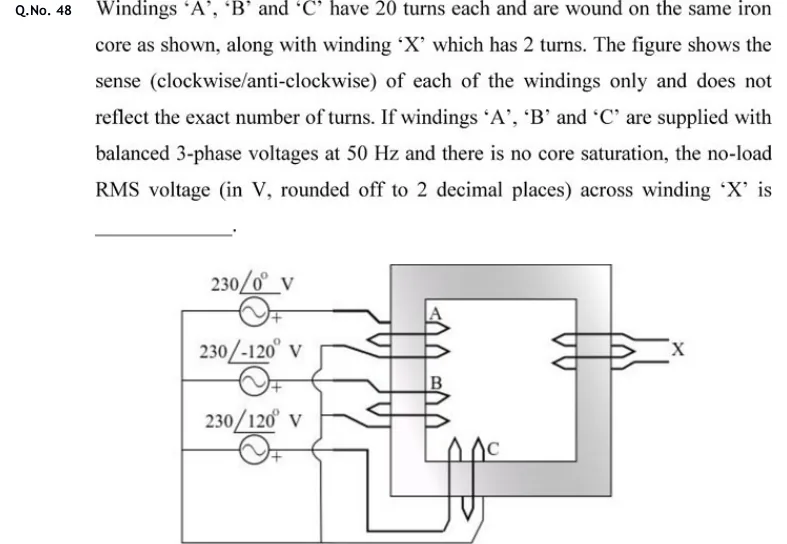
Windings 'A', 'B' and 'C' have 20 turns each and are wound on the same iron core as shown, along with winding 'X' which has 2 turns. The figure shows the sense (clockwise/anti-clockwise) of each of the windings only and does not reflect the exact number of turns. If windings 'A', 'B' and 'C' are supplied with balanced 3-phase voltages at 50 Hz and there is no core saturation, the no-load RMS voltage (in V, rounded off to 2 decimal places) across winding 'X' is ______.
 Tap to open full size
A single square window-type iron core (one closed magnetic loop), drawn shaded. Windings A (upper) and B (lower) are on the left limb and drawn identically: each has two rightward chevrons inside the window and one leftward chevron outside the limb. Winding C is on the bottom limb, with two upward loops inside the window and one downward loop below the core. Winding X is on the right limb, with two leftward chevrons inside the window and one rightward chevron outside, and two open leads marked X. On the left are three ideal sinusoidal sources, each with its '+' terminal on the right: 230∠0° V, 230∠−120° V and 230∠120° V. The '+' terminal of each source goes to one end of A, B and C respectively. The other ends of the three windings go to a common return line, joined to a left-hand bus that connects the other terminals of all three sources. So each winding is connected directly across its own source.
Official answer: marks to all candidatesSource: Official answer key, GATE 2020 EE (IIT Delhi)
A single-phase 100 kVA, 1000 V / 100 V, 50 Hz transformer has a voltage drop of 5% across its series impedance at full load. Of this, 3% is due to resistance. The percentage regulation of the transformer at full load with 0.8 lagging power factor is
4.8
6.8
8.8
10.8
A 3-phase 900 kVA, 3 kV / √3 kV (Δ/Y), 50 Hz transformer has primary (high voltage side) resistance per phase of 0.3 Ω and secondary (low voltage side) resistance per phase of 0.02 Ω. Iron loss of the transformer is 10 kW. The full load % efficiency of the transformer operated at unity power factor is ________ (up to 2 decimal places).
PRACTICE
A single-phase transformer has 400 turns on its primary winding. The core flux is sinusoidal with a peak value of . The rms emf induced in the primary winding is ______ V.
Answer: (accepted range )
EMF equation: .
. (Using in place of 4.44 gives .)
In the short-circuit test on a single-phase transformer, one winding is shorted. The voltage applied to the other winding is raised from zero until rated current flows, and this turns out to be only a small percentage of rated voltage. Which statement correctly explains this and its consequence for the wattmeter reading?
The voltage is limited to protect the wattmeter from magnetising inrush current
The leakage impedance is small, so rated current flows at a low voltage; the core flux, and hence the core loss, is then negligible and the wattmeter reads essentially the copper loss
The low voltage allows the magnetising reactance to be measured accurately
The test must be performed at reduced frequency, which requires a reduced voltage
Answer: (B)
The only impedance limiting the current is the small series (leakage) impedance , so rated current is reached at , a small fraction of rated voltage.
The core flux is proportional to the applied voltage, so it is also small. The core loss therefore becomes negligible, and the wattmeter reads essentially the copper loss at the test current. Option B.
A is false: magnetising inrush occurs when a transformer is switched onto rated voltage, which this test never applies. C is false: the SC test does not give ; the OC test does. D is false: the test is run at rated frequency.
A single-phase transformer has and , both referred to the secondary. It delivers its rated secondary current of at its rated secondary voltage of to a load of power factor lagging. Using the first-order approximate formula, with regulation expressed as a percentage of the rated secondary voltage, the voltage regulation is ______ %.
Answer: (accepted range )
Lagging load: , with and .
.
.
For comparison, the exact phasor sum gives . The question asks for the first-order value.
Two three-phase transformers of different kVA ratings are to be connected in parallel. There must be no circulating current at no load, and the load must divide between them in proportion to their kVA ratings. Which of the following conditions are required?
The same rated line-voltage ratio on both transformers
The same phase sequence and the same phase displacement between HV and LV line voltages
Identical kVA ratings
Equal per-unit impedance, each on its own kVA rating, with equal X/R ratio
Answer: (A), (B), (D)
A: a different line-voltage ratio makes the open-circuit secondary voltages unequal, which drives a circulating current even at no load. Required.
B: a different phase displacement or phase sequence puts a large voltage difference around the loop and drives a heavy circulating current. Required.
C: not required. Units of different ratings can share load in proportion to their ratings.
D: the load divides as , which is proportional to the ratings only when . Equal keeps the two currents in phase, so the units can together deliver the sum of their ratings. Required.
A single-phase auto-transformer steps a supply down with voltage ratio . It is compared with a two-winding transformer of the same output and voltages, designed with the same current density and mean length of turn. What fraction of the two-winding transformer's winding copper does the auto-transformer save?
25%
50%
75%
90%
Answer: (A)
Copper ratio: .
Saving , i.e. . Option A.
Trap: (option C) is the copper the auto-transformer still uses, not the copper saved.
A single-phase transformer has a core loss of and a full-load copper loss of . Its efficiency is maximum when the load is ______ kVA.
Answer: (accepted range )
Maximum efficiency occurs when the copper loss equals the core loss: .
.
Load . This does not depend on power factor.
(At unity power factor, .)
OFFICIAL GATE 2027 SYLLABUS WORDING
Copied from the GATE 2027 syllabus; see all 2027 syllabi.
GATE EE
Single phase transformer: equivalent circuit, phasor diagram, open circuit and short circuit tests, regulation and efficiency; Three-phase transformers: connections, vector groups, parallel operation; Auto-transformer
GATE IN
Single phase transformers
Preparing in Kolkata? IAE Academy's course for GATE EE or GATE IN.